In the past, turbine blades had to be ground on seven machines in turn, but now they can be machined in one setup on a single grinding unit. In this way, the adjustment time and production run time can be reduced by more than half, and the grinding cost can be reduced by 1/3.
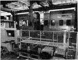
In Munich, we develop, manufacture and maintain components for transmissions and transmissions. These transmissions and components are used on aircraft and stationary gas turbines. Since 1991, we have facilitated the grinding of turbine running blades (working blades) with highly automated, computer-controlled grinding units (Fig. 1).
Despite some problems in the application and management of this complex machine tool, important technical and economic goals can still be achieved. Therefore, it plays a fundamental role in improving competitiveness on an international scale.
In 1987, our production leaders decided to purchase three highly automated grinding machines from Blohm GmbH for the machining of turbine rotor blades and stator blades (guide blades). The reasons for deciding to make such a huge investment are as follows:
It is predicted that demand will continue to grow in this area, and pressure from international competition will continue to increase; strive to achieve quality improvement (reduced waste and repair processing); international competitors use similar machine tools (such as Pratt & Whitney in the US) And the UK's Rolls Royce Co., Ltd., etc.; the trend of highly automated manufacturing equipment (CIM) is widely used in the manufacturing industry.
The first two grinding units were used in turbine rotor blades in 1991 and 1992. Due to technical problems and temporary user reductions, the third grinding unit was not put into use until 1997. The machining is similar to units 1 and 2, (as opposed to the plan). Technically, after the guide vane grinding is not possible, the rotor blades are also machined.
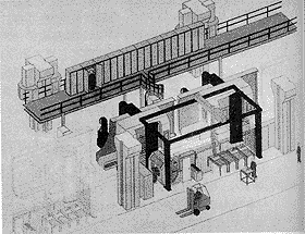
The concept of the “grinding unit†and the boundary between it and the traditional grinding machine can be seen at a glance by looking at the basic equipment components: it uses two twin-spindle grinding machines, GC2000, each with up to three grinding wheels (Elbe) Co., Ltd., manufactured by Tyrolit Co., Ltd.), each machine can digitally control 16 axes (4 of which are toolholder coordinates and grinding head coordinates, 4 are the coordinates of the wheel dressing equipment for forming the grinding wheel, 4 are two The swivel coordinates of the indexing heads, and the other four are the linear coordinates of the coolant nozzles. A multi-position measuring device is also integrated in the grinding unit, with up to 60 measured values ​​and a measuring process. They have feedback on the measurement results and automatic correction of the CNC axes (Figure 2), as well as an optical reading system for identifying the workpiece. The grinding unit is also equipped with a cleaning and drying station for cleaning the workpiece before the measuring cycle. The workpiece is transferred between the stations by a gantry robot with 4 control axes. The flow between the various components is controlled by a unit computer.
All measured values ​​and process data are sent to a higher-level unit master computer. Further data processing and archiving are carried out here. The entire process can be observed and monitored on the console.
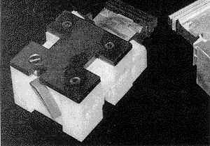
Before starting the grinding process, each turbine blade is cast into a rectangular, hexahedral piece (see Figure 3). This casting has nothing unique, just to meet the processing needs of the grinding unit. Industrial robots are capable of handling such highly complex workpieces and can withstand the enormous forces generated during the grinding process. In addition, since only four different sizes of castings are used, the type of clamping device required can be greatly reduced. The casting block is then fitted with a bar code so that the component can be identified in the grinding unit. During this time, the laser label will be bonded by a simple adhesive that can be pressed in the field.
Use deep grinding technology with continuous dressing. The grinding wheel is continuously trimmed with a diamond wheel (Winter & Sohn); the axes can be adjusted according to the amount of wear. For turbine blades of commonly used nickel-based materials, a high cutting rate can be achieved with this method (Fig. 4).
However, only the optimum combination of machining parameters, grinding wheels and diamond rollers can shorten the machining time, extend the tool life and have a good processing quality. After solving the initial problems with several products, you can achieve a fairly satisfactory situation.
The clamping device is mounted on a CNC double turntable. It moves the workpiece from the loading position to the machining position. Between the various grinding processes, the workpiece is automatically exchanged for clamping, if one set cannot be completed in one set.
The grinding wheel is pre-formed on the machine after automatic exchange and balanced. The exchange library is managed by the host computer. And during the grinding wheel exchange process and after the exchange, the necessary safety and various non-interfering operations in the process are carried out.
After the grinding process, the casting block is heated and unnecessary parts of the workpiece are "melted". Next, the workpiece is cleaned and the residue in the casting block alloy is analyzed by an expensive analytical method (AAS atomic absorption test). Even a small amount of residue can cause rapid fall of the turbine blades.
The application of the grinding unit has led to dramatic improvements and rationalization efforts. Specifically, with the grinding unit, it is possible to reduce the grinding cost by approximately 35%. An operator can monitor the operation of the equipment from the console.
However, without the optimization and improvement that has been ongoing in recent years, this highly automated and complex device is unlikely to achieve this.
In 1997, the grinding unit was shortened from 24 weeks to 9 weeks compared to the first grinding unit in 1991. By properly changing the guards of the machine's peripherals, the maintenance and service intervals for some components can be extended by about 80%. In addition, the utilization rate of machine tools has also increased from 75% to 92% (6 days a week, 3 shifts per day).
In addition to shortening the processing time, seven grinding machines can be reduced to one grinding unit, which further plays a rational role in production. In this way, the workpiece can be completely machined using a grinding unit. This also reduces the continuous processing time, shortens the path of workpiece transport during processing and reduces the floor space of the shop. By reducing the number of times the workpiece is clamped during machining and managing online measurements with the CNC axis, the quality of the process can be greatly optimized, thereby greatly reducing scrap and additional costs, and optimizing the cpk value to 1.5A to 4.0.
Of course, there are certain problems with the grinding unit. For example, it requires a higher batch size to enable cost-effective manufacturing (approximately 400 pieces in batch size). In addition, it cannot escape from interference. Due to the inherent complexity of the grinding unit, it is not possible to change the type of workpiece in a short time. It requires higher equipment costs. In addition, casting technology is constantly evolving, that is, turbine blade machining is being eliminated more and more, because the size casting can already be performed, so the grinding unit application may be reduced. The key boundary for economic applications is approximately four processing steps, as it is not necessary to go beyond a known "basic processing time".
Finally, such devices cannot be integrated into independent manufacturing islands. The problem is also the way the process-oriented team works. In addition, it requires a high total investment and corresponding capital.
The basic differences between the grinding unit and the conventional grinding machine are shown in Table 1.
The use of grinding units gives our turbine blades in Munich a strong international competitive edge. However, its advantages can only be fully realized after a long period of operation and through the improvement of the operator.
Future investments in the field of grinding require full consideration of the required flexibility, changes in the organization of the workshop (team work, manufacturing island production), progressive casting techniques (removal of grinding by size casting) and other methods It is carried out with less investment funds and the like. The first way is to make an island layout that includes small, low-cost grinders. This type of grinding machine requires fewer operators.
International competitiveness
In Munich, we develop, manufacture and maintain components for transmissions and transmissions. These transmissions and components are used on aircraft and stationary gas turbines. Since 1991, we have facilitated the grinding of turbine running blades (working blades) with highly automated, computer-controlled grinding units (Fig. 1).
Despite some problems in the application and management of this complex machine tool, important technical and economic goals can still be achieved. Therefore, it plays a fundamental role in improving competitiveness on an international scale.
In 1987, our production leaders decided to purchase three highly automated grinding machines from Blohm GmbH for the machining of turbine rotor blades and stator blades (guide blades). The reasons for deciding to make such a huge investment are as follows:
It is predicted that demand will continue to grow in this area, and pressure from international competition will continue to increase; strive to achieve quality improvement (reduced waste and repair processing); international competitors use similar machine tools (such as Pratt & Whitney in the US) And the UK's Rolls Royce Co., Ltd., etc.; the trend of highly automated manufacturing equipment (CIM) is widely used in the manufacturing industry.
|
|
| Figure 1 Computer controlled grinding unit | |
The first two grinding units were used in turbine rotor blades in 1991 and 1992. Due to technical problems and temporary user reductions, the third grinding unit was not put into use until 1997. The machining is similar to units 1 and 2, (as opposed to the plan). Technically, after the guide vane grinding is not possible, the rotor blades are also machined.
|
|
Grinding unit structure
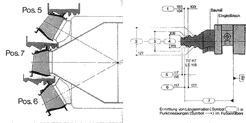
The concept of the “grinding unit†and the boundary between it and the traditional grinding machine can be seen at a glance by looking at the basic equipment components: it uses two twin-spindle grinding machines, GC2000, each with up to three grinding wheels (Elbe) Co., Ltd., manufactured by Tyrolit Co., Ltd.), each machine can digitally control 16 axes (4 of which are toolholder coordinates and grinding head coordinates, 4 are the coordinates of the wheel dressing equipment for forming the grinding wheel, 4 are two The swivel coordinates of the indexing heads, and the other four are the linear coordinates of the coolant nozzles. A multi-position measuring device is also integrated in the grinding unit, with up to 60 measured values ​​and a measuring process. They have feedback on the measurement results and automatic correction of the CNC axes (Figure 2), as well as an optical reading system for identifying the workpiece. The grinding unit is also equipped with a cleaning and drying station for cleaning the workpiece before the measuring cycle. The workpiece is transferred between the stations by a gantry robot with 4 control axes. The flow between the various components is controlled by a unit computer.
All measured values ​​and process data are sent to a higher-level unit master computer. Further data processing and archiving are carried out here. The entire process can be observed and monitored on the console.
Adopted technology
Before starting the grinding process, each turbine blade is cast into a rectangular, hexahedral piece (see Figure 3). This casting has nothing unique, just to meet the processing needs of the grinding unit. Industrial robots are capable of handling such highly complex workpieces and can withstand the enormous forces generated during the grinding process. In addition, since only four different sizes of castings are used, the type of clamping device required can be greatly reduced. The casting block is then fitted with a bar code so that the component can be identified in the grinding unit. During this time, the laser label will be bonded by a simple adhesive that can be pressed in the field.
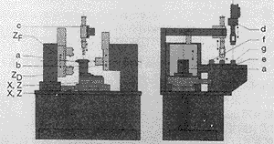
Use deep grinding technology with continuous dressing. The grinding wheel is continuously trimmed with a diamond wheel (Winter & Sohn); the axes can be adjusted according to the amount of wear. For turbine blades of commonly used nickel-based materials, a high cutting rate can be achieved with this method (Fig. 4).
|
X and Z coordinate axes Z D band side Z F base belt side Z coordinate axis
However, only the optimum combination of machining parameters, grinding wheels and diamond rollers can shorten the machining time, extend the tool life and have a good processing quality. After solving the initial problems with several products, you can achieve a fairly satisfactory situation.
The clamping device is mounted on a CNC double turntable. It moves the workpiece from the loading position to the machining position. Between the various grinding processes, the workpiece is automatically exchanged for clamping, if one set cannot be completed in one set.
The grinding wheel is pre-formed on the machine after automatic exchange and balanced. The exchange library is managed by the host computer. And during the grinding wheel exchange process and after the exchange, the necessary safety and various non-interfering operations in the process are carried out.
After the grinding process, the casting block is heated and unnecessary parts of the workpiece are "melted". Next, the workpiece is cleaned and the residue in the casting block alloy is analyzed by an expensive analytical method (AAS atomic absorption test). Even a small amount of residue can cause rapid fall of the turbine blades.
Experience and results
The application of the grinding unit has led to dramatic improvements and rationalization efforts. Specifically, with the grinding unit, it is possible to reduce the grinding cost by approximately 35%. An operator can monitor the operation of the equipment from the console.
However, without the optimization and improvement that has been ongoing in recent years, this highly automated and complex device is unlikely to achieve this.
In 1997, the grinding unit was shortened from 24 weeks to 9 weeks compared to the first grinding unit in 1991. By properly changing the guards of the machine's peripherals, the maintenance and service intervals for some components can be extended by about 80%. In addition, the utilization rate of machine tools has also increased from 75% to 92% (6 days a week, 3 shifts per day).
In addition to shortening the processing time, seven grinding machines can be reduced to one grinding unit, which further plays a rational role in production. In this way, the workpiece can be completely machined using a grinding unit. This also reduces the continuous processing time, shortens the path of workpiece transport during processing and reduces the floor space of the shop. By reducing the number of times the workpiece is clamped during machining and managing online measurements with the CNC axis, the quality of the process can be greatly optimized, thereby greatly reducing scrap and additional costs, and optimizing the cpk value to 1.5A to 4.0.
| standard | Grinding unit | Ordinary grinding machine |
| Number of machine tools | 1 | 7 |
| Technology availability (%) | 92 | 94 |
| Productivity (pieces/month) | 4500~6000 | 5000 |
| Floor area (m 2 ) | 200 | 300 |
| Path of workpiece transport during processing (m) | 350 | 750 |
| Batch size (piece) | 400 | 400 |
| Familiar with time (days) | 9 | 20 |
| Adjustment time (min) | 90 | 200 |
| Grinding costs (German mark / piece)* | 100 | 150 |
| Investment cost (German mark)* | 100 | 40 |
| Maintenance costs (German mark / h)* | 100 | 140 |
| Inferior goods (DPM)* | 60 | 100 |
| Process reliability (cpk) | 1.5 to 4.0 | 1.3~2.0 |
| Personnel use (three shifts)* (workers) | 50 | 100 |
| * The displayed value, not the conclusive data for possible absolute costs | ||
Of course, there are certain problems with the grinding unit. For example, it requires a higher batch size to enable cost-effective manufacturing (approximately 400 pieces in batch size). In addition, it cannot escape from interference. Due to the inherent complexity of the grinding unit, it is not possible to change the type of workpiece in a short time. It requires higher equipment costs. In addition, casting technology is constantly evolving, that is, turbine blade machining is being eliminated more and more, because the size casting can already be performed, so the grinding unit application may be reduced. The key boundary for economic applications is approximately four processing steps, as it is not necessary to go beyond a known "basic processing time".
Finally, such devices cannot be integrated into independent manufacturing islands. The problem is also the way the process-oriented team works. In addition, it requires a high total investment and corresponding capital.
The basic differences between the grinding unit and the conventional grinding machine are shown in Table 1.
Manufacturing island processing trends
The use of grinding units gives our turbine blades in Munich a strong international competitive edge. However, its advantages can only be fully realized after a long period of operation and through the improvement of the operator.
Future investments in the field of grinding require full consideration of the required flexibility, changes in the organization of the workshop (team work, manufacturing island production), progressive casting techniques (removal of grinding by size casting) and other methods It is carried out with less investment funds and the like. The first way is to make an island layout that includes small, low-cost grinders. This type of grinding machine requires fewer operators.
Polyamide Resin,Alcohol Polyamide Resin,Synthetic Resin
Dingnan Songyuan Chemical Co., Ltd. , http://www.jxresin.com
