Friction clutches are important components in mechanical design for shaft-to-shaft connections that cause them to rotate together and transmit torque. They have the advantages of smooth joints, low impact and low vibration. The important part of the friction linings is designed in a variety of different styles depending on the application. However, due to poor working conditions and severe wear and tear, it is required to be large. At present, many small companies are targeting this market, but due to the limitations of equipment conditions, some measures must be taken in the production process to be manufactured quickly and economically. The following examples are given.
Process analysis
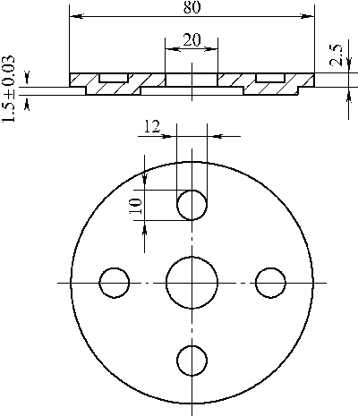
In the technical business contracted by our company, there is a shape as shown in Figure 1, such as a gasket, and a friction plate with four bosses is formed in the middle. It is made of 2.5mm thick 45 steel plate after heat treatment of 45~52HRC, and the production batch is large.

This is a blanked and formed composite part. Due to the large production volume, punching and forming composite molds should be used according to the part structure. Calculate the formula according to the punching force:
P = KLtτ
Where τ——shear strength, take 500N/mm2
L——the circumference of the blank, mm
T——material thickness, mm
K - safety factor, take 1.3
Substituting part related data, you can calculate:
Friction plate punching force P=1.3×3.14×(80+20)×2.5×500=510kN
According to the empirical formula of punching and blanking discharge force: P unloading = K unloading P
In the formula K unloading - for the discharge force coefficient, take 0.06
P —— punching, blanking total punching force, N
Substituting part related data, you can calculate:
Friction plate discharge force P unloading = 0.06 × 510 = 30.6kN
Calculate the formula based on the forming force:
P = KLtσb
Where σb——material tensile strength, take 65kg/mm2
L——the circumference of the formed part, mm
T——material thickness, mm
K——for the forming factor, take 0.8
Substituting part related data, you can calculate:
Friction sheet forming force P = 0.8 × 2.5 × (10 × 2 + 12 × 2) × 4 × 65 = 229 kN
Therefore, the friction, punching, blanking and forming composite force of the friction plate is: 510+30.6+229=770kN, and it is natural to select a press of 770kN or more.
According to the other production equipment, only JC23-40 open double-column tilting press can be selected. If punching, blanking and forming compounding are required, the punching pressure is obviously insufficient. For example, the compounding process is adjusted to a single step in step-by-step implementation. It will definitely reduce production efficiency and increase costs.
According to the structure of the part, the forming height is 1.5mm less than the material thickness t=2.5mm, so the forming of the boss can only be achieved by the extension of the material itself and the thickness of the material; and because the distance between the convex part and the inner edge of the part is greater than (3~ 3.5) t = (7.5 ~ 8.75) mm, so it does not cause the edge material to shrink inward, resulting in forming defects.
The above analysis shows that only four bosses are partially formed. During the blanking, punching and forming process of the parts, the forming of the bosses does not have the necessary sequence.
Mold design
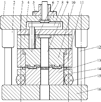
According to the characteristics of the forming of the part and the selected JC23-40 press with the material of the crossbar, the mold shown in Fig. 2 was designed.

1. Upper template 2. Guide sleeve 3. Backing plate 4. Fixing plate 5. Mold handle 6. Top rod 7. Drill rod 8. Drilling plate 9. Punching punch 10. Unloader
11. Blanking die 12. Guide post 13. Punching, forming convex and concave die 14. Discharge plate 15. Polyurethane block 16. Lower template
The whole mold working process is: the blank is placed at the appropriate position of the mold, the punch slider starts to move downward, and the blanking die 11 and the unloading plate 14 jointly press the blank, and as the punch slider moves downward, the blanking die 11 Working with the punching and forming convex and concave die 13, when the slider is further moved down by 3 mm, the shape of the part is punched out. At this time, the top of the unloader 10 is just in contact with the bottom end of the fixed plate 4, and when the slider continues to move downward by 1.5 mm, The unloader 10 and the punching punch 9 cooperate with the punching and forming convex and concave die 13 to complete the forming of the four central bosses and the punching of the intermediate φ20 mm holes. At this point, the inside of the part, the shape and the boss are completely formed.
The slider moves up, the hitting rod 7 collides with the press strut, and the unloading force is transmitted to the battering plate 8 via the striking rod 7, and then transmitted to the unloader 10 via the ejector 6, by the unloader 10 The processed part is pushed out of the blanking die 11 cavity, and at the same time, the strip of the finished shape is acted upon by the unloading plate 14, the top material is completed, and the remaining material is transferred to the next working cycle.
In the mold, the unloader has the dual function of forming the boss and unloading. In order to prevent the unloader from rotating, it is designed as a square structure with guiding and positioning, and it guarantees a single-sided gap of 0.03~0.05 with the blanking concave cavity. Mm to ensure accurate forming and reliable discharge.
The height dimension of the forming boss is determined by the associated forming dimensions of the unloader. By grinding and punching and forming the upper plane of the convex and concave mold, the forming height dimension can be adjusted to ensure the forming precision.
Effect and conclusion
After the mold design is completed, the parts produced and tested will meet the requirements of the drawings at one time. After more than three years of use, the production of tens of thousands of parts, product quality and reliable mold work.
Here, the reason why the small tonnage press can process the parts at one time can be seen from the working principle of the mold mainly due to the design of the mold structure, the blanking die 11 is 3 mm thicker than the unloader 10, and the punching punch 9 is falling. After the die 11 is contacted with the blank 3 mm to form a stepped punching, after the blanking die 11 is finished blanking, the unloader and the punching punch begin to contact the blank, and then form and punch. At this time, the punching force is P=1.3×3.14×80×2.5×500=408 kN, which is slightly larger than 400 kN, and it is only necessary to select a slightly larger blanking gap to overcome.
The adoption of the above measures has re-arranged the “rhythm†of blanking, punching and forming compounding, forming a stepped pressure distribution, thereby eliminating the pressure superposition after the three composites, so that the press can be blanked and punched. The contradiction of insufficient forming and compounding force has been fundamentally resolved.
In the actual production, in addition to the step-type punching, different oblique blade structures are used on the punch and the die to form a beveled edge punching, which can reduce the punching force by 40%~80%, but the structure of the blade is manufactured and Grinding is more complicated, and the cutting edge is easy to wear. It is mainly suitable for large and thick workpieces. If the surface quality of the workpiece is not high, hot stamping can be used. The heat resistance can significantly reduce the shear strength of the material, and the convex and concave gaps such as punching or stretching can be appropriately increased, and the punching force can be well reduced. It has the effect of processing large parts with small tonnage presses.
Author: Lin Chang-Lin Group Machines Corporation / Shan Zhong Xiang
Sea Valve,Sea Water Gate Valve,Marine Sea Valve,Steel Right Angle Sea Valve
Jiangsu Hida Marine Valve Co., Ltd , https://www.haidavalve.com