1 Structural features of planer milling and boring machine
Long hole boring, represented by the coaxial hole system of the box parts, is one of the most important contents in metal cutting. Although there are still examples of long hole boring using stencils, guide bushings, bench-top milling boring machines, post-supporting long masts, or manual aligning workpieces by 180°, in recent years, on the one hand, due to CNC milling and boring machines and The machining center is used in a large amount, which makes the coordinate positioning accuracy of various horizontal milling and boring machines and the accuracy of the table rotation indexing greatly improved. The long hole boring is gradually rotated by the high-efficiency table by 180° self-aligning boring head (Fig. 1) replaced; on the other hand, the mass production and application of ordinary or CNC planer milling and boring machine for the layout of the bed, from the machine structure, the table is rotated 180° self-aligning boring, almost become the machine tool The only way to cut long holes.
|
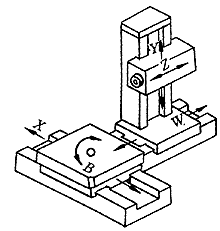
Planer milling and boring machines and bench-top milling and boring machines have no different functions from function to movement in the tool system. The difference between the two is mainly in the five coordinates of x, y, z, W and B for forming various workpiece profiles. Give the structure of the two coordinate movements of x and W in motion. The two-layer structure (horizontal bed-sliding-rotary table) laid on the horizontal bed part of the planer milling and boring machine completes the x (horizontal) direction with the three-layer structure table of the bench-top milling and boring machine. The W (vertical) direction and the B (stage rotation) move differently to the three coordinate movements, and only the two coordinate movements of the x-direction and the B-direction are completed, and the movement of the W-direction coordinate motion is realized by the movement of the vertical bed portion along the shape of the column carrying the headstock. . The structure of its coordinate system is shown in Figure 2. Obviously, when boring on a planer milling bed, the movement of the tool relative to the workpiece (including the main motion and the feed motion) is a tool, and the workpiece is stationary. The movement of the boring tool can be realized by a é•— axis that is directly moved along the z axis when the column is fixed to a longitudinal position on the longitudinal bed, or after the é•— axis has a certain elongation value, along the W axis. The straight column is realized.
|
2 Coaxiality error of the column feeding into the boring head and its compensation
- Concentricity error of the column feeding into the boring head D 3
- If the center point O 1 of the tool tip is just above the nominal axis of the bore, it indicates that the column longitudinal line coincides with the nominal axis of the bore. At this time, the two creping points of the boring d 1 and d 2 holes before and after turning around the head are above the nominal axis of the hole, and the feeding path is the same section of the column along the W axis, so the axes of the two holes d 1 and d 2 coincide. It is a straight line with no concentricity error.
- If the center point O 1 of the tool tip is not on the axis of the hole and deviates from the line value error d y 3 along the y coordinate direction, the two holes of d 1 and d 2 are respectively punctured before and after turning the head, twice The defects are not above the nominal axis of the pupil, but because the two starting points are still the same point, and the two feeding paths are also the same segment in the y upward direction, so d 1 and d 2 The axes of the holes still coincide with the same straight line and there is no coaxiality error.
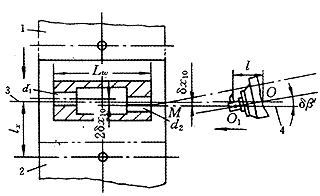
- When the center of rotation O 1 of the tool tip is not on the axis of the hole and deviates from the line value error d x 3 in the x-coordinate direction, the condition of the head is adjusted as shown in FIG. It can be seen that the two axes of the two portions d 1 and d 2 of the growth hole before and after the adjustment of the head are respectively arranged on both sides of the nominal axis of the pupil, and the distance between each axis of the hole is d x 3 , thereby causing The coaxiality error D 3 of the long hole. According to the concept of coaxiality
In the formula db ′—the intersection angle error between the nominal axis of the pupil and the longitudinal line of the columnD 3 =4 d x 3 =4ltg db ' (1)
L——the distance from the center point of the tool tip to the intersection of the two lines. If the column longitudinal line does not intersect with the nominal axis of the hole, but is parallel, and the spacing is also d x 3 , intersect with the two lines shown. The effect of the transaction angle error db ' is the same. - Determination of D 3 compensation value D x 3
The main factors affecting the coaxiality of the boring head of the planer milling and boring machine are the same as the bench-top milling and boring machine. It is also the indexing error da of the 180° turning head of the table and the half-length d 1 axis that has been formed before the turning. After turning the head again, it coincides with the axis of the boring shaft and boring the other half hole d 2 of the long hole, and the required table horizontal (x) direction moves the positioning error d x 2 of L x = 2l x (Fig. 1). Moreover, the inclination error df generated by the table in the xy coordinate plane before and after the table is rotated by 180°, the inclination error dy generated in the yz plane and the translation error d y generated in the y direction are also the same as the planer milling and boring machine. An important factor in the concentricity. However, the influence of the spatial position of the yaw axis on the coaxiality of the boring head is usually the same as that of the bench boring machine which is used for the full length boring of the boring hole.
If the vertical (or horizontal) line of the table is modeled on a bench-top milling and boring machine, the point on the axis of the table that is equal to the axis of the hole is the trajectory of the table when it is moved vertically (or horizontally). The trajectory center point O 1 of the boring tool tip on the boring axis of the table boring machine and the axis of the boring axis is defined as the column longitudinal line when the column is moved straight along the W coordinate. The planer milling and boring machine of the boring, whether the nominal axis of the boring is parallel or intersects with the vertical line of the column (there are very few cases where the two are coincident), the feeding trajectory of the boring head mounted on the boring bar That is, the axis of the hole actually formed by the boring tool should be parallel to the W coordinate axis under the condition that the linearity error of the vertical displacement of the column and the drape error caused by the mast feeding are not counted. Therefore, in the feeding form of the boring head, the straightness of each half of the holes d 1 and d 2 before and after the turning of the head has no linearity error, and whether the full hole length is coaxial, the d 1 and d 2 holes are seen. Whether the two axes coincide in a straight line. D 1 and d are coincident with the bore axis 2 two, depends mainly on the tip of the boring tool if the rotational center O is just above the nominal axis of the bore 1.
|
This coaxiality error is a fixed value error, which can be traversed after the d 1 hole table is rotated 180° and traversed by L x = 2l x according to the determined compensation value D x 3 and its direction. This D x 3 value eliminates this concentricity error. Can be seen from Figure 3
| D x 3 =2 d x 3 | (2) |
If the nominal axis of the pupil is just within the yW coordinate plane (longitudinal plane) of the axis of the table, then the boring head can no longer traverse 2l x distance after the head turning, thus eliminating D 3 The concentricity error can also eliminate the influence of the positioning error d x 2 of the traverse 2l x on the concentricity of the boring head.
Therefore, it can be concluded that under the premise that the workpiece has been clamped to a reasonable position on the workbench, the optimal clamping position of the planer milling and boring machine table on the horizontal bed is to place the center point of the table rotation. The intersection of the nominal axis of the pupil and the longitudinal line of the column. When the nominal axis of the boring hole cannot be just past the center of rotation of the table due to the structure of the machined part, the reasonable position of the table on the horizontal bed should be to traverse the table to the center of rotation of the boring tool tip. 1 , just above the nominal axis of the workpiece being bored.
3 Reasonable determination of the longitudinal position of the column when the boring shaft is fed
- Determination of the optimal position of the column in the longitudinal direction
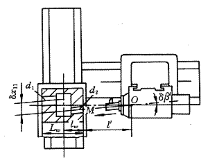
- l W - the distance from the front end of the hole to the center of rotation of the table
- l'——The distance from the hole end to the intersection point M of the two lines. The l' value can be positive or negative. When the O point is inside the M point, the l' value is negative, and when it is outside (the position shown), l' is positive.
- Obviously, D 4 can be compensated by n-shifting the table before boring the d 2 hole. The compensation value is
D x 4 = d x 4 = 2(l W +l')tg db (4) 
Figure 4: The shaft is fed into the bore
Equation (3) shows that in the presence of db , the necessary and sufficient condition for eliminating D 4 is l W +l'=0. It can be seen from Fig. 4 that under the premise that the workpiece has been in a reasonable position (the full length of the traverse line of the traverse line), it is only necessary to satisfy the equation l W + l' = 0. The intersection O of the axis of the axis and the axis of the borehole is located just on the traverse line of the center of rotation of the table. Since the intersection point O of the above two lines moves longitudinally along the column as the column is longitudinally moved, the conditional expression l W + l' = 0 can always be established. That is to say, when the boring shaft of the planer milling and boring machine is fed into the boring hole, in order to minimize the D 4 , the optimum position of the column clamped on the longitudinal bed should be the intersection point of the axis of the boring shaft and the nominal axis of the hole, just located. The center of rotation of the table is on the traverse line.- The measurement of the angular error d b and the intersection point O is known from the above, and the premise of obtaining the optimal clamping position and accurate compensation of the column is the position of the known db and the intersection point O on the axis of the yaw axis, which can be obtained by actual measurement, and the measurement method is as follows .
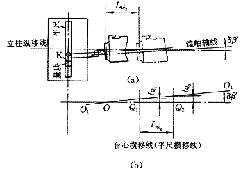
Place the workbench in the horizontal middle position, place a flat ruler on the table top, and place a gauge block on the upper side of the flat center of the workbench (Fig. 5). The column is stopped at a suitable position, and the dial gauge is fixed on the boring shaft. The head is placed on the side K of the gauge block. The dial gauge reading A 1 is taken , and the boring axis and the table are rotated by 180°. If there is no indexing error, the head will still take the reading B 1 on the original side K, and take the axis of the 镗 axis as the reference line (O 1 ~O 1 ), thereby determining a point Q 1 on the longitudinal line of the column. The distance from Q 1 to the axis of the yaw axis is l Q 1 = (A 1 - B 1 )/2. Vertical uprights must pay attention shift line Q represents a boring point is the axis of which side l 1 Q sign.- Longitudinal movement of the column L W 2 , the 镗 axis also forwards or retreats L W 2 , repeats the previous measurement to obtain l Q 2 =(A 2 -B 2 )/2, thus determining the Q 2 point. By connecting Q 1 and Q 2 , a straight line Q 1 Q 2 representing the column longitudinal line is obtained, as shown in Fig. 5b, so that the angle db of the axis of the 镗 axis and the longitudinal line of the column and its intersection point O can be directly measured to the headstock. The path value of the front end face.
- If A 1 =B 1 is measured, then l Q1 =0, indicating that the point on the longitudinal line of the column is on the axis of the spindle; if A 2 =B 2 is measured, it indicates that the two lines coincide; if l Q 1 is calculated =l Q 2 , then the above two lines are parallel. If l Q 1 ≠l Q 2 , the two lines intersect, and the intersection angle db can also be calculated by the following formula:
Tg db =(l Q 2 -l Q 1 )/l W 2 (5) - The L W 2 value in the equation can be obtained by recording the W coordinate indication value.

Figure 5 Measurement intersection point O and db- The position of the intersection point O on the axis of the yaw axis is obtained by the actual measurement to obtain the position of the intersection axis of the é•— axis and the vertical line of the column (that is, the nominal axis of the boring), and it may not be possible to feed the boring shaft into the boring hole. l The condition of W +l'=0. For example, if the intersection point O intersects the axis portion behind the front bearing of the boring shaft, even if the column is moved forward to the front extreme position of the longitudinal direction, it is impossible to make the intersection point O just at a reasonable position on the traverse line of the center of rotation of the table. Therefore, it can be known that the reasonable position of the longitudinal direction of the column can be realized without failing, and it must be ensured that the intersection point O is to be specifically transferred to the workpiece side of the front bearing of the boring shaft, and the intersection point of ensuring l W + l' = 0 is obtained. The specific location. When the shank is determined, the distance from the center of rotation of the tool tip to the front bearing is known, and the specific value of the reasonable position of the intersection point O is not difficult to find.
Since the size of d b and the position of the intersection point O on the axis of the 镗 axis are determined by the relative positional accuracy of the headstock mounted on the column and the column being fixed on the carriage, the intersection point O should be determined. After the proper position on the axis of the boring axis, it is necessary to adjust the assembly position of the headstock on the vertical rail of the column or adjust the position of the column relative to the sliding seat (so that the column is slightly rotated by an angle around the y-axis on the sliding seat). The intersection point O has the requirement of a suitable position. - l'——The distance from the hole end to the intersection point M of the two lines. The l' value can be positive or negative. When the O point is inside the M point, the l' value is negative, and when it is outside (the position shown), l' is positive.
When faced with a specific situation, the planer milling and boring machine must fix the column to a suitable position on the longitudinal bed, and the axis of the boring shaft and the nominal axis of the boring are used when the boring shaft is extended with the tool as the feeding form of the boring. The intersection error d b in the xz plane, the intersection error dg in the yz plane, as with the bench-top milling and boring machine, has an important influence on the coaxiality of the boring head, and as the length of the boring shaft increases, The downward deflection of the mast caused by the weight of the yaw axis also has a great influence on the coaxiality of the boring of the boring head. Unlike a table-top milling and boring machine, when the boring shaft of the planer milling boring machine protrudes from the boring hole, the longitudinally movable column must be fixed to a certain position on the longitudinal bed, and it is important that this determined position can and should be select.
According to the design regulations, the movement distance of the é•— axis along the z direction should be parallel to the movement of the column along the W axis; the nominal axis of the boring should be placed parallel to the W(z) axis. The front table of the boring has been moved along the x coordinate to align the nominal axis of the boring to the boring axis, and the clamping is fixed. The boring shaft has been retracted to the zero position, and the shank of the clamping boring tool is inserted into the inner cone hole of the boring shaft. (Figure 4). When there is an intersection error d b in the xz plane by the nominal axis of the pupil and the axis of the yaw axis, since the vertical intersection of the two lines along the vertical rail of the bed also moves along the longitudinal line of the column, In 4, the value of l' changes accordingly, and the intersection angle db of the two lines remains unchanged. Therefore, no matter which position the column is moved to, the calculation formula of the concentricity error D 4 of the U-turn pupil caused by db can be expressed as
| D 4 =2 d x 4 =4(l W +l')tg db | (3) |
4 Reasonable determination of tool position on planer milling and boring machine
When the column is used to feed the boring head on the planer milling and boring machine, the boring tool clamped on the arbor of the boring shaft has a reasonable position along the Z direction, on the one hand, it needs to meet the fulcrum center of the shank to the front end surface of the spindle box. The distance is slightly larger than half of the total length of the hole (the small hole will not be able to pass through the long hole, if it is too large, the rigidity of the boring shaft will decrease); on the other hand, the center of rotation of the tool tip should be placed on the axis of the yaw axis and the column is longitudinally displaced. The intersection of the lines is on O.
Measuring Tape,Smart Measuring Tape,Mini Measuring Tape,Retractable Measuring Tape
Shangqiu Hengli Measuring Tools Co.,Ltd , https://www.henglimtools.com


