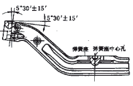
The front axle of the automobile processed by our factory has more specifications. The two ends of the front axle main pin hole of each specification are arranged on the horizontal milling machine for milling. Due to the long front axle, loading and unloading on the machine tool is difficult and often affects the tempo of the production line. Since the front end of the front axle pin hole has an inclined angle and the inclination angles are not equal (see Figure 1), special clamps are required for each type of front axle. This increases the manufacturing cost of the front axle and extends the manufacturing cycle of the front axle, which does not meet the needs of the market. To this end, we conducted a site survey of the front axle of the car machined by our factory, and found that the distance between the two spring seats on the front axle of each type is close or equal; the change of the inclination angle of the end faces of the main pin hole is also small. Between 3 ° ~ 7 °. In this way, a universal fixture can be made. When processing the front axles of different specifications, it is sufficient to replace several special components, which can reduce the manufacturing cost of the fixture.
In order to meet the production cycle, the factory decided to design a special machine tool to machine the two ends of the front axle pin hole. In order to reduce the manufacturing cost, it was decided to use the old parts such as the power head of the warehouse to manufacture special planes, and the effect was very good.

figure 1
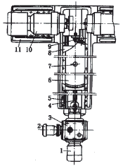
 1. Fast-forward motor 2. Work-in motor 3. Gearbox 4. Screw 5. Guide 6. Workbench 7. Locating pin 8. Mechanical slide 9. Adjusting bolt 10. Power head 11. Bed figure 2 |
1 Structure of special machine tools
The structure of the special machine tool is shown in Figure 2. It is mainly composed of the bed, the power head, the work table, the mechanical slide table and other components. The power head 10 is mounted in a T-shaped groove above the bed 11 and can be moved to the left and right by a certain distance to fit the front axle of different specifications. It consists of a motor, gearbox, milling cutter and other components. After adjusting the relative positions of the two power heads as needed, the power head is bolted. In order to prevent the power head from being displaced by the reaction force of the workpiece during operation, which affects the machining accuracy, the bed has an adjusting bolt to tighten the motor seat on the power head. The rotating shaft on the power head allows the milling cutter to move slightly in the left and right direction to achieve the desired working position. The table 6 is mounted on the slide table 8, and there is a nut under the table, and the power is transmitted by the screw. The table 6 has a positioning pin 7 fitted to the Clamp, and the positioning pin has an annular T-shaped groove at the front and the rear. The front end of the table has a longitudinal T-shaped groove; the rear end has a vertical scribe line and passes through the center of the positioning pin 7. The motor 1 advances the table and the motor 2 advances the table. The travel switch under the workbench is used to control the work cycle of the worktable fast forward, work forward, and fast reverse.
2 fixture structure
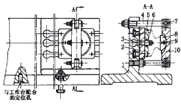
The fixture structure is shown in Figure 3. It mainly consists of clip specific, movable board, positioning board and so on. The lower part of the clamp body 1 has a hole at the center to match the shaft on the table, and is connected to the table by a T-bolt. The upper part of the clip is symmetrical at both ends, and the T-shaped groove is not too long. The left end of the clip is evenly engraved with an angular index value to indicate that the clamp can be rotated by a certain angle. The joint bolt 4 is installed in the open groove at the upper end of the clip, and the other joint bolt is fixed on the clip. The movable plate 2 is connected to the clamp body 1 through a T-shaped bolt, and can be moved to the left and right by a certain distance on the clamp. There are two positioning keys 3, which are fixed on the movable plate 2 by screws and are used for positioning. The positioning pin 6 is mounted on the movable plate 2 (the other end of the clip is a trimmed pin). The positioning plate 5 is screwed to the movable plate 2. The pressure plate 10 is hingedly connected, and the floating pressure block 8 on the pressure plate 10 is directly pressed against the blank surface of the front shaft. Considering that there is a burr left by the die forging on the symmetry center line of the blank, a groove is formed on the contact surface of the floating block 8 and the front shaft. The floating clamp 8 is connected to the pressure plate 10 via a shaft 9. The floating compact 8 is able to make a small rotation about the shaft 9. Due to the long distance between the spring seat and the king pin hole, the workpiece may vibrate when both ends of the main pin hole are milled. To this end, a bracket is installed near the main pin hole (Fig. 4). The bracket is skewed and mounted on the T-slot at the front end of the machine table. The two bolt holes on the bracket are staggered, not in a straight line, but the two T-bolts are in a T-slot.
 1. Clip specific 2. movable plate 3. positioning button 4. joint bolt 5. positioning plate 6. positioning pin 7. hinge shaft 8. floating clamp 9. shaft 10. plate image 3 |  1. support frame 2. screw Figure 4 |
3 Fixture adjustment
According to the process requirements, first adjust the distance between the two positioning pins (one cylindrical pin and one chamfered pin). Look at the scale rotation clamp to the desired angle. Tighten the bolts to secure the parts. Then, the front axle sample is lifted and placed on the fixture so that the center holes on the two spring seats cooperate with the cylindrical pin and the chamfered pin, respectively. After fixing the position, tighten the nut on the joint bolt to fix the front axle. During the process of fixing the front axle, the floating clamp on the pressure plate first contacts the high point on the front axle blank surface. As the pressure plate continues to press the front axle, the high point on the blank surface forces the floating compact to make a small circle around the connecting shaft. Rotation until the floating clamp contacts the blank face on both sides of the shaft. Then screw the upper and lower screws on the bracket so that they both touch the front axle. At this time, the machine is started, so that both ends of the front axle main pin hole enter the cutting range of the power head. Stop turning the machine and fine-tune the two power heads so that the disc cutters on the power head touch each end of the front axle.
Then take off the sample and install the front axle to be machined, then you can start the normal processing.
When processing the front axle of other specifications, just replace the two positioning pins and adjust the distance between the two movable plates. The movable plate with the cylindrical pin has a left-right movement range of less than 25 mm, and the movable plate with the trimmed pin can be moved to the left and right. The workpiece can be machined by rotating the clamp to the desired angle, adjusting the position of the bracket, and adjusting the distance between the two milling cutters.
Pan Head Drilling Screws With Tapping Screw
Pan head self-tapping screw with self-drilling tip, usually fixing metal elements to each other, or plastic, wood and other materials on metal. Pan Head Drilling Screws With Tapping Screw can be used for thicker materials than sheet metal screws, such as thin-walled rolled and drawn profiles. The thread is identical to the screws in the sheet.
Pan head drilling screws with tapping screw are a type of fastener that have a flat, circular head with a slightly rounded top and a flat underside. These screws are designed to be used with a drill or power tool for easy installation.
The pan head refers to the shape of the screw head, which resembles a shallow pan. This design allows for a larger surface area to distribute the force applied during installation, reducing the risk of the screw head sinking into the material being fastened.
The drilling feature of these screws means that they have a self-drilling tip, often referred to as a drill point or self-tapping point. This point is designed to cut through the material being fastened, eliminating the need for pre-drilling a hole. This feature makes installation quicker and more efficient, as it combines the drilling and fastening steps into one.
Pan head drilling screws with tapping screw are commonly used in applications where a secure and durable fastening is required. They are often used in construction, woodworking, metalworking, and other industries. These screws can be used with a variety of materials, including wood, metal, and plastic.
In summary, pan head drilling screws with tapping screw are versatile fasteners that have a flat, circular head and a self-drilling point. They are designed for easy installation with a drill or power tool and are commonly used in various industries for secure and efficient fastening.
Pan Head Drilling Screws With Tapping Screw,Pan Head Screw Self Tapping,Pan Head Tapping Screw,Black Pan Head Self Tapping Screws
Taizhou Wanluo Hardware Products Co., Ltd. , https://www.wlhardware.com