Different mechanisms exist in different stages of fatigue failure process. Therefore, the study of fatigue failure mechanism usually studies the mechanism of crack initiation and expansion. On the other hand, there are many internal and external factors that obviously or potentially affect the fatigue damage process, making it difficult to explain the mechanism of complex and variable fatigue damage with a unified theory. So far, research on fatigue failure mechanism has achieved some results, and some models about fatigue crack initiation and expansion have been proposed, and the corresponding theories are expounded. Each of these theories has its own characteristics and can explain some of the fatigue damage under certain conditions. This section provides an overview of several of the more popular theories. With the deepening of research in this field, the mechanism of fatigue damage will achieve more systematic and better results.
I. Mechanism of fatigue crack initiation
Although the mechanism of fatigue crack initiation is various, for the case of no surface defects, the basic mechanism of fatigue crack initiation is slip nucleation. The plastic deformation of the local area is a prerequisite for the formation of the rifting, and the alternating part of the stress is the key factor for the formation of fatigue cracks.
1. Reciprocating slip to form an extrudate and a model for extruding into the trough: The model is shown in Figure 6-56. The model considers that the basic mechanism of fatigue crack initiation is slip nucleation. In most cases of fatigue fracture, The cleavage system is formed from the surface. If a sample is taken from the inside of the sample subjected to a certain fatigue cyclic stress, the fatigue strength is not lower than the fatigue strength of the raw material, which indicates that the material inside is not subjected to substantial during the fatigue process. damage. If the surface of the sample is strengthened, the fatigue strength can be improved. Conversely, if the surface of the test piece is softened, the fatigue strength should be reduced, which indicates the direct influence of the surface quality on the fatigue strength. Further analysis shows that the formation of fatigue cracks is related to a series of structural changes occurring inside the specimen during fatigue. The prerequisite for crack formation is local plastic deformation on the surface. For smooth specimens, after a thousand cycles of fatigue cyclic loading, a small amount of slip line appears on the surface of the specimen. As the test continues, slippage occurs. The line will continue to increase, the amount of slip will gradually increase, and the slip line formed later will mostly abut the original slip line, and together form a slip belt, the slip belt will become wider and deeper. If the surface layer is removed by chemical etching or electropolishing, a part of the slip line will disappear, but some of the coarser slip bands will remain and gradually widen in the subsequent continuous cycle to form a so-called dwelling slip. Transfer. Continue to circulate and leave the slip belt and widen it, eventually initiating fatigue cracks on these resident slip belts.
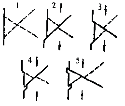
Figure 6-56 “Squeeze†and “Extrusion†model formed by reciprocating slip
Many materials produce "squeeze" and "squeeze" when the slip zone is large, forming ridges and grooves on the surface, or strips of squeezing. Dimensions up to 10μm, strip length from 1μm mountain to grain size. The amount of extrusion and extrusion increases with the increase of the cycle. After a certain size, crystallographic slits or cracks are formed under the surface of the groove or "crowded" and "extruded", and gradually expand into macroscopic visible cracks. . This extrusion and extrusion phenomenon can occur in copper, aluminum, iron, and alloy steel.
The formation of the resident slip zone is related to stress and is formed only in low stress and high cycle fatigue, while in high stress and low cycle, the crack is along the crystal.
The slip condition is related to the yield strength of the material. The material with low yield strength is easy to produce a slip zone during the fatigue process. The well produces fatigue cracks on the resident slip belt or in the crowded and extruded parts, and the yield strength is higher. The more difficult the slip is, the fatigue crack is not easy to sprout.
In the presence of a coherent counterfeit, the resident slip zone usually occurs preferentially here and leads to the initiation of fatigue cracks. Figure 6-57 shows the fatigue cracks formed by copper at the intersection of the sliding zone and the twin boundary of the fatigue condition. This phenomenon may be related to the “crowding-extrusion†at the intersection of the slip zone and the twin boundary. .
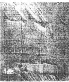
Figure 6-57 Fatigue cracking of copper under cyclic loading
The boundary of polycrystalline metal is also the area where fatigue cracks are easy to initiate. Figure 6-58 shows the fatigue cracks that are initiated on the iron grain boundaries. Intensive slip marks are formed in the narrow region near the fatigue crack. Figure 6-58c shows that the fatigue cracks that are initiated on the grain boundaries are also the result of a large amount of slippage of the crystal.
2. Dislocation Destruction Theory: A short and thin slip line is produced in the initial stage of the fatigue process, as shown in Figure 6-59, which can be considered as the accumulation of dislocations caused by the resistance at both ends. Therefore, the source of the dislocation on the slip surface is stopped, and the slip line cannot be developed. When cross-slip occurs between the two slip lines that are relatively close, the dislocations accumulated on the slip surface are dissipated, and the dislocation source on these surfaces continues to move, and the slip line continues to develop into a slip belt. See Figure 6-59(b). On the two parallel sliding surfaces (less than 10-7cm apart), the opposite signs of the two columns are eliminated, leaving a row of holes as shown in Figure 6-59(c). This hole will absorb more The dislocations enter and develop into a fatigue crack.
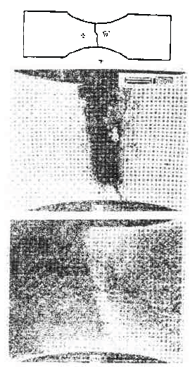
Figure 6-58 α-iron sample with two grains in the bending fatigue process (grain boundary and external force perpendicular) fatigue cracks in the grain boundary
(a) Schematic diagram of A, B twin crystal samples; (b) Surface of fatigued specimen; (c) Surface polished and etched surface

Figure 6-59 Fatigue crack formation dislocation mechanism
Second, the expansion mechanism of the first stage of fatigue crack growth
The fracture surface of the first stage of fatigue crack propagation is mostly a flat and flat flat surface. X-ray analysis proves that in the face-centered cubic metal, the flat section is {111}. Initially, it is in the same direction as the maximum shear stress, and the direction is slightly changed after the grain boundary is encountered in the expansion. Gradually transition to a direction perpendicular to the maximum tensile stress. Some materials, such as Al-7.5% high-strength aluminum, can observe a serrated section in the first stage of crack propagation, which is the result of the development of the first stage slip along the {111} plane in different orientations. It can be seen that the main feature of the first stage of fatigue crack propagation is along a specific slip surface, which is the {111} plane in the body-centered cubic metal. The fracture is flat and smooth, indicating that the expansion of the first stage is caused by the alternating slip under the action of alternating stress, which causes the crack to expand. Now, there are mainly the following models describing the first phase of the expansion.
1. Plastic passivation model: According to the model, under the action of alternating stress, in the half cycle of tensile stress, the crack tip is opened and passivated due to plastic rheology, thus forming a new surface and cracking forward. . During the half cycle of the compressive stress, the crack recloses. When a cycle is completed, the crack advances by ΔC distance. When the tension is repeated alternately, the crack continues to expand forward, as shown in Figure 6-60. Since the expansion of the first stage of the crack is very small, the amount of expansion per cycle is very small, so there is no trace other than scratches on the surface. This model requires the front end of the crack to flow along the two sets of slip surfaces in the direction of the shear head, so it is suitable for materials that have a striated slip.
2. Non-slip model: This model is based on the fact that most of the materials have no fatigue-grain on the first-stage section. It is believed that the crack propagation is strictly along a slip surface. It is a kind of Pure shear (no staggered slip) is controlled by the process. As shown in Figure 6-61. First, the metal on one side of the crack is displaced by shearing, so that the distance from the surface of the other metal to the crack tip is increased from C1 to C2, and then under a compressive load. The surface of the sample was restored to its original state.
At this time, the crack length is increased from C1 to
 ,surface
  .
. 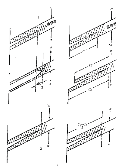
Figure 6-60 Plastic passivation model for crack first stage expansion Figure 6-61 First stage expansion model for "non-slip" crack
In essence, the above two models are not fundamentally different because the crack propagation they describe is achieved by creating new surfaces with the same plastic displacement. But the non-slip model is suitable for those plane slip materials.
3. "Combination weakening" model: This is a model proposed for nickel-based superalloys. The model assumes that under high-cycle fatigue loading, the slip surface of the crack front (a small number of slip surfaces) is produced. Repeated slip movement. This slipping motion weakens the atomic bonding force between the slip surfaces. When this weakening effect is large enough in the local area before the crack tip, local low stress fracture occurs under the action of normal stress, and the crack spreads forward a short distance, leaving a so-called "solution" without significant plastic deformation. As a schematic diagram, see 6-62.
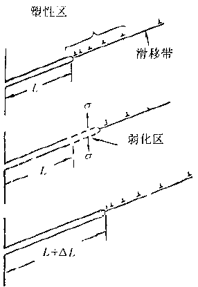
Figure 6-62 "Combine weakening" model of the first phase of expansion
This model also explains the characteristics of the first stage of low-cycle fatigue extension of nickel-base superalloys.
Under high strain, the local part of the crack tip will undergo severe deformation, and the deformation band will widen. Under the maximum stress, micro-pit type plastic fracture will occur in the local area. Thereby leaving a pit on the section.
Third, the mechanism of the second stage of fatigue crack growth
Fracture crack propagation The second stage fracture is the most prominent part of fatigue characteristics. In the general fatigue fracture, it accounts for most of the crack propagation area, and its remarkable feature is fatigue striation. Therefore, the mechanism of fatigue crack propagation in the second stage is mostly related to the formation mechanism of fatigue fringes. Several models are now introduced.
Plastic passivation model
This is a model proposed after studying the cross section of pure aluminum and pure nickel high strain crack propagation. The schematic diagram is shown in Figure 6-63.
When the load is not applied, the crack shape is as shown in (a). Under the tensile stress of the loading section, the crack is opened, and the two small incisions at the front end of the crack concentrate the fine shift on the slip zone at an angle of 45° to the plane of the crack. The slip bands are perpendicular to each other, as in (b). When the tensile stress reaches a maximum value, as in (c), the effect of stress concentration due to deformation of the crack disappears, the fine band of the crack front becomes wider, and the front end of the crack is passivated, which is semi-circular, and a new surface is generated in the process. And make the crack spread forward. Thereafter, it is transferred to the second half of the load and slides in the opposite direction along the slip belt. In Figure (d), the crack front ends are pressed against each other, and the new surface formed during the loading half cycle is pressed toward the crack plane, and a part of the crack occurs. The formation of a new incision (Fig. e) results in a new fatigue striation with a C distance. In this cycle, the cracks continue to expand forward, and fatigue fringes are continuously formed.
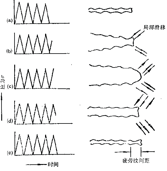
Figure 6-63 Crack propagation second stage plastic passivation model
According to this model, the crack propagates continuously forward, and in essence, it is amorphous, and on the other hand, it does not require expansion in a polycrystal because it does not require a certain crystallographic plane. There are grain boundaries and inclusions, and the symmetry of the above-mentioned crack front-end slip zone may be difficult to satisfy. Due to the relationship of the crystallization degree, those slip systems that are likely to slip are at an angle that is not symmetrical with the front end of the crack. At this time, the expansion is slightly different from the above-mentioned ideal mechanism. The process is shown in Figure 6-64. .
First, the crack often forms an asymmetrical secondary crack as shown in (a) under the compressive load. When the tensile stress acts, the deformation of the front end of the crack is mostly concentrated at the foremost crack. Under the maximum tensile stress, a shape as shown in (b) is formed. Finally, under the compressive load, the shape of the front end of the fatigue crack is shown in Fig. (c), which is consistent with the fatigue fringes (the mountains and valleys do not correspond to each other) actually observed in Fig. 6-3l, (3) and (4).
In summary, the basic idea of ​​this model is the plastic passivation and stress relaxation at the front end of the crack.
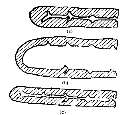
Figure 6-64 Non-crystallographic ductile fatigue pattern forming mechanism
2. Formation mechanism of crystallographic ductile fatigue striation
After a detailed study of some models characterized by ductile fatigue ridges, a crystallographic ductile fatigue ridge formation mechanism as shown in Fig. 6-65 was proposed.
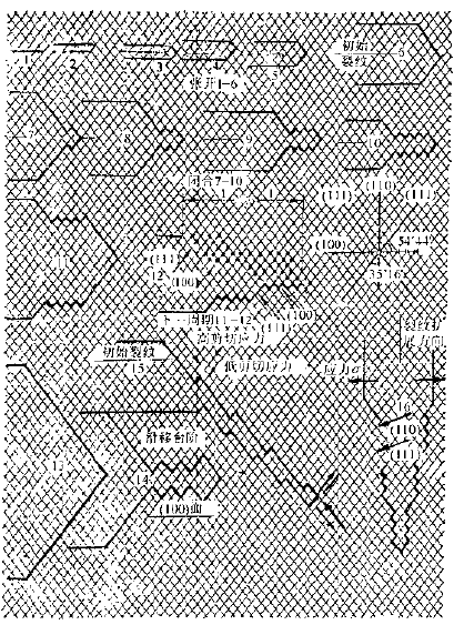
Figure 6-65 Formation mechanism of crystallographic toughness fatigue
The simplest is the l-10 stage in the figure. In the loading section, the crack spreads forward along the slip direction of the two slip systems {111}, while passivating the crack front. Slip can move one atomic distance along each slip surface along the two slip systems at the same time, or it can be continuously slipped on a slip system until the machining hardening of a certain program is generated, and then it is transferred to another On a slip system, it slides on both systems in the same way. Since the new slip surface is used for crack propagation, the two slip systems will alternately activate.
During the unloading phase, the slip will be reversed, which will make the crack front sharper again and prepare for the expansion of the next cycle. If the reverse slip happens to occur on the slip surface at the front end of the crack. Then stage (6) in the figure will return to stage (1). However, since the free surface (crack surface) newly generated in the loading section is already oxidized, it is impossible to reverse the original crystal plane along the front end of the crack. Instead, it will slip along many new parallel crystal planes. If the slip amount of each atomic layer is numerically equal to a Brinell loss, the newly generated surface in the reverse slip process must be a smooth crystallographic plane. (stage 12). However, this situation is relatively rare. It is more likely that a number of Brinell vectors will slip on a few specific slip surfaces, and as a result, there will be many steps on the newly created crack face, as shown in stage (13) (14).
For high-strength aluminum alloys, the angle of intersection between two non-parallel slip faces (111) may be 109°28' or 70°32'. If the (111) plane is slipped along two angles of intersection 109°28', the crack propagation is as shown in stages 1-12. If the slip surface is slipped along the 70° 32' angle of intersection, the crack propagation is as shown in stage 16.
The model shows that the amount of crack propagation per cycle occurs in the loading segment. During the unloading phase, the newly generated crack surface forms a fatigue glow due to the slip surface, and the crack front end is sharpened again, and is also prepared for the second half cycle.
Up to now, when we describe the model, we assume that the two (111) faces act equally well for crack propagation, and thus the cracks expand along the bisector plane of the angle between the two slip surfaces. If the amount of slip provided by the two slip systems for crack propagation is not equal, the crack will expand away from the bisector of the two slip faces, as shown in stage (15).
According to the above model, (i) the fatigue fringes on both sides of the fatigue crack should correspond to peak-peak, valley-valley. (ii) When the loading crack is opened, the slip is very uniform, and when the crack is closed, the slip will be much irregular, so the front side of the fatigue fringe (ie the tooth surface formed when closed) should be There are coarser and more visible sliding steps, while the rear side is smaller and the dislocation distribution is more complicated. (iii) in the case of symmetric slip, the macroscopic plane of crack propagation is parallel to the (100) or (110) plane, and the sides of the fatigue glow are (111) planes, if the crack is closed, each atomic layer The slip amount is equal to one Brinell vector, and the front side of the fatigue glow is changed to the (100) or (110) plane (stages 12 and 16). (IV) If the crack propagation deviates from the bisector due to the asymmetrical slip, the fatigue ridge on both sides of the fatigue crack will be different, that is, on the side of the maximum shear stress, the depth/width ratio of the fatigue ridge To be larger than the other side (stage 15). The above four points are confirmed by some experimental observations.
Due to the different materials, the shape of the fatigue embossing may vary greatly in the microscopic range. So the explanation about its formation mechanism is far from being completely solved. Many people have proposed several new models from different angles.
3. Formation mechanism of brittle fatigue
The formation of brittle cleavage fatigue ridges is not as complex as ductile fatigue ridges. The basic process is that under the action of fatigue load, the cleavage surface is first cleavage a small distance, and then the plastic deformation surface at the front end of the crack stops expanding. When the next cycle begins, it also acts as a cleavage fracture, so that it reciprocates, that is, a cleavage fatigue glow is formed. Figure 6-66 is a schematic diagram of a mechanism for cleavage fatigue striation formation.
Assuming the initial shape of the crack is as in (a), as the load increases, the crack front extends a distance forward due to cleavage fracture, as in (b). Then plastic passivation stops cleavage. Since the material of the cleavage fracture is sufficiently hardened, the deformation is concentrated in the very narrow slip band of the crack front, as indicated by the two broken lines of (c). When the crack is fully opened under load, the shape of the front end is as shown in (d). Then, when the load is loaded or compressed, the crack is closed and the front end is sharpened again to form a shape (c) similar to (a). Therefore, the most basic idea as a cleavage fatigue striation forming mechanism is also related to the plastic passivation process.
The mechanism for forming the amorphous crystal fragile fatigue embossing can be applied by cutting the cleavage in the cleavage fatigue embossing mechanism into a quasi-cleavage fracture.
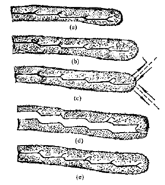
Figure 6-66 Formation mechanism of cleavage fatigue wrinkles
Third, the factors affecting the two stages of crack propagation
In addition to the difference in materials, there will be differences in the two-stage distribution of crack propagation, and there are other factors that significantly affect the two-stage transition and distribution. Here are some of the main factors.
1. The effect of fatigue strain amplitude
For most metallic materials, as the strain amplitude increases, it will be detrimental to the expansion of the first phase and facilitate the expansion of the second phase. The smoothness of the first-stage section formed under low cycle and high strain fatigue is worse than that of the high cycle and low strain. It consists of a number of (111) facets that are parallel to each other but at different heights. The length of each facet is between about 0.1 and 0.4 mm, so the entire section is much higher than the circumferential fatigue section. Steps and rivers are not visible on the electron micrograph of the fracture, but are covered with evenly distributed and similarly sized pits, as shown in Figure 6-67.
2. The effect of temperature
The effect of temperature on the crack propagation pattern is significant. There are data showing polycrystalline superalloys such as Udimet, Mar-M200
Alloys, below 760 ° C, their fatigue fracture is a distinct first-stage expansion of the wearable type. The temperature will affect the slip mode. There are two types of slippage in general village materials: flat slip and wavy slip. A planar slip is a set of slip surfaces that are parallel to each other. The wavy slip is staggered along two mutually non-parallel slip surfaces. Planar slip is beneficial to the first stage expansion, staggered slip is beneficial to the second stage expansion, high temperature alloy is increased from 760 °C to 925 °C, the parallelism of slip disappears, and the sliding shift dominates, which is beneficial to the second. Stage expansion. Therefore, as the temperature increases, the single crystal alloy will be transformed from the first stage expansion to the second stage expansion.
For polycrystalline gold, the high temperature creep increases with increasing temperature, causing grain boundary sliding and cavity formation, resulting in fatigue crack propagation along the grain boundary. There will be many pits on its section. The characteristics of the first stage of crack propagation and fatigue fringes are not seen. Table 6-1 lists the fatigue crack nucleation positions and extended paths at three temperatures (Udimet700 low cycle fatigue).
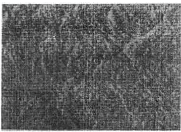
Figure 6-67 Low-cycle fatigue first stage fracture morphology 10700χ transmission electron microscope replica
Table 6-1 Effect of temperature on Udimet700 during low cycle fatigue

3. The effect of alternating frequency
The occurrence of two stages of fatigue crack growth of high temperature materials and the conversion frequency have a great relationship with the alternating frequency of stress. The low frequency is conducive to the emergence of the second phase, while the high frequency is beneficial to the maintenance of the first phase of the expansion mode. For example, in the 760 ° C high cycle fatigue test of Udimet 700, if the stress conversion rate is 2 weeks/minute, the fatigue crack expands in the second stage. If the frequency is 60,000 cycles/min, it is almost the first stage. The way to expand, the intermediate frequency, such as 60 weeks / min, then the transition between the first phase and the second phase.
The effect of frequency on the two stages of fatigue fracture is through the change in strain rate. For the same material, the greater the strain rate (ie, the higher the stress frequency), the more difficult the transition is, and thus the first stage of expansion. The strain rate will increase as the crack length increases (in the case of constant stress), so as the crack expands, there is a tendency for the second stage expansion to the first stage expansion mode.
The basic function of the Solder Preform Feeder is to flatten the solder thin or wire and produce solder plates. The use of the solder plate is to add thickness to some components that requires more solder content. The purpose of the feeder is to lessen the cost by taking out costings on component reels or other solutions that is currently implemented in SMT production process. KDW Solder Preform Feeder can be customized to any SMT Mounter brand and models. Currently, the Solder Preform Feeder is now available and passed machine compatibility test for SMT Machine brands such as Juki, Samsung, Fuji, Yamaha, Panasonic, and Siemens.
SMT Solder Preform Feeder, Solder Plate Feeder, Solder Preform Feeder, Automatic Solder Preform Feeder
ShenZhen KDW Electronics Co.,Ltd , https://www.smtsplicetape.com