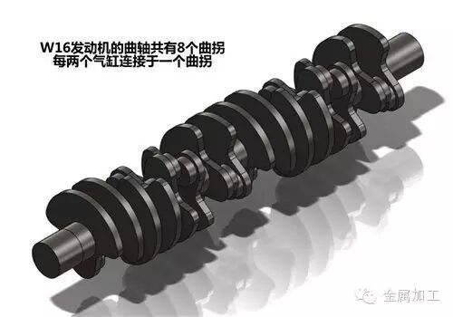
At present, in the processing of key parts of automobile engines, the process and level of automatic processing of cylinder and cylinder head flexible processing are slightly higher. For many people, it seems that the cylinder block and cylinder head are the most critical parts of the engine, and many machine tool builders spend most of their energy on this. In fact, the technical content of the crankshaft processing flexible line is higher than that of the cylinder and cylinder head flexible production line. The flexible line of cylinder block and cylinder head is mainly composed of machining center, and the flexible production line of crankshaft not only has machining center, but also CNC machine, crankshaft oil hole CNC drilling machine, undercut groove CNC rolling machine, CNC external milling machine, CNC lathe. Pulling machine tools, CNC grinding machines and belt grinding machines, etc., can be described as many and difficult, from the equipment.
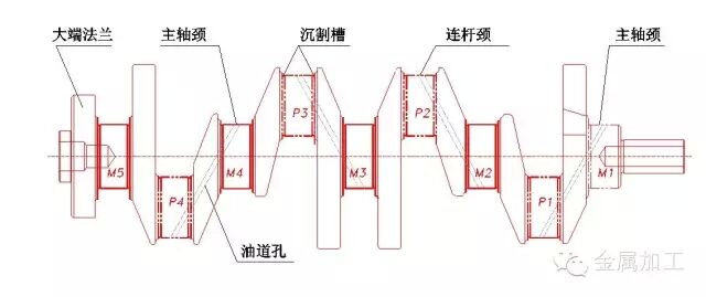
Crankshaft processing technology and overall layout of flexible lines
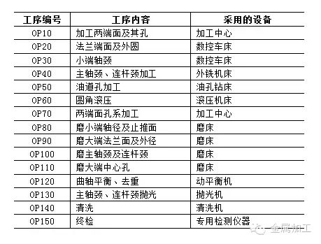
Since the numerical control of machine tools, high-speed, high-efficiency machining technology and equipment have been widely adopted in the automobile manufacturing industry, and the production efficiency has been greatly improved. The number of production equipment on the engine crankshaft production line is rapidly decreasing, although the equipment for machining the crankshaft is very specific. However, it has become increasingly flexible, processing crankshafts of different specifications, as long as the machine tool can be adjusted to achieve variable varieties of processing, which is a major advancement in today's crankshaft processing technology. Due to the different types of automobiles, the specifications of the crankshaft are different, and the equipment and process methods used are also different. The table below shows a crankshaft machining process.
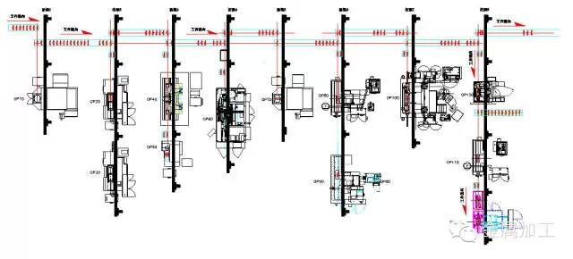
Crankshaft flexible automatic processing line (partial)
Crankshaft flexible machining automatic lines usually adopt the layout structure of trunk and branch transportation. The trunk transport uses a segmented alternate ground transport format, while the branch uses a truss manipulator for airborne transport. The truss manipulator is used to increase the conveying speed and accuracy, and the conveying position is arbitrarily changed by the control program, thereby realizing the alternate conveying of the trunk road. On each branch road, the truss manipulator grabs the crankshaft conveyed from the main trunk road to the machine where the branch road is located for processing. After processing, the crankshaft is then taken to the inspection station for inspection. After passing the test, it is then placed under the main road. On a conveyor belt, the conveyor belt transports it to the next process, and the unqualified crankshaft is placed in the unqualified area. The manual is determined according to the unqualified condition and type to decide whether to repair or scrap.
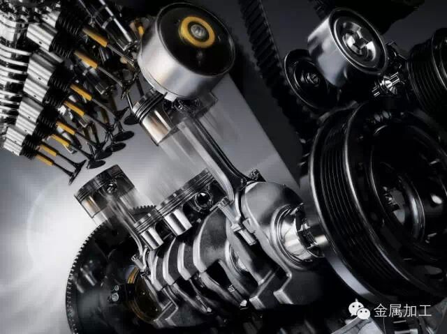
Crankshaft automatic line key processing technology and equipment
1) Crankshaft main journal and connecting rod neck milling The current CNC external milling machine adopts a modular design, which makes the external milling CNC machine have a variety of different structures that can be deformed to meet the needs of crankshaft specifications. When machining the crankshaft parts, due to the structure of the disc milling cutter itself, the cutting edge and the workpiece are always in intermittent contact with impact. Therefore, the gap is controlled in the entire cutting system of the machine tool, which reduces the vibration generated by the motion gap during the machining process, thereby improving the machining accuracy and the service life of the tool.
The outer milling machine can be composed of two outer milling cutter discs, which can also swing up and down while doing the main motion cutting, so as to adapt to the needs of processing the connecting rod neck. At this time, the crankshaft rotates, the connecting rod neck rotates around the center of the main journal, and the milling cutter disc oscillates up and down with the rotation of the connecting rod neck to realize follow-up cutting. Since the two milling heads can be moved along the spindle axis, milling of each of the main journal and the connecting rod neck of the crankshaft is completed.
Case 1: Recommended for external milling cutters
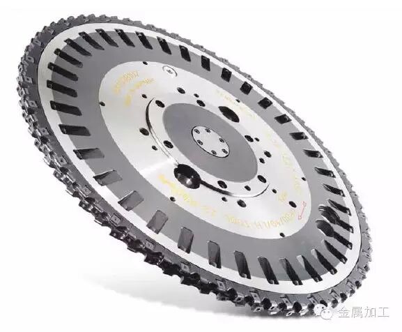
• Single or multi-disc design • ISO standard blade and custom design perfect balance to meet customer requirements and the most economical solution • Cutting conditions based on customer requirements, range from Vc=80-300m/min, fz=0.05-0.50 Mm
2) Crankshaft main journal and connecting rod neck grinding
At present, with the development of machine tool manufacturing technology, the grinding of the connecting rod neck adopts the tracking grinding method. The tracking grinding method uses the center line of the main journal as the center of rotation, and the grinding of the crankshaft connecting rod neck is completed in one clamping (also used for spindle neck grinding). The realization of grinding the connecting rod journal is controlled by CNC. The feed of the grinding wheel and the rotary motion of the workpiece are linked in two axes to complete the machining of the crankshaft. The tracking grinding method uses a single clamping and grinding of the crankshaft main journal and the connecting rod neck in sequence on a numerically controlled grinding machine, which can effectively reduce equipment costs, reduce processing costs, and improve machining precision and production efficiency.
Case 2: Grinder recommendation
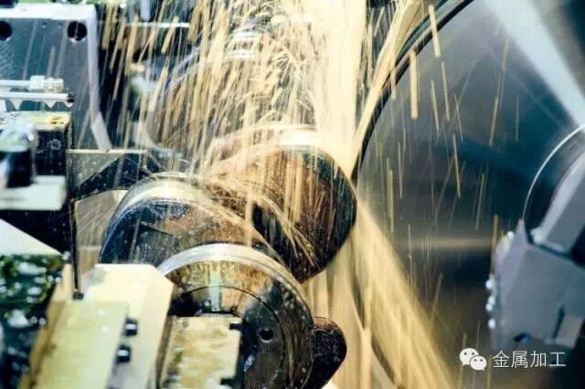
• Improve quality and reduce beats. Whether it is a single-cylinder or a twelve-cylinder shaft or a coarse grinding of various crankshafts of different sizes, JUCRANK can easily handle workpieces up to 4.8m in length and weighing up to 1000kg. The two grinding wheel heads are equipped with Z-axis and X-axis respectively, which can perform different grinding processes at the same time. When one grinding spindle is grinding the main journal, the other grinding spindle oscillates back and forth in the X-axis direction of the connecting rod journal.
JUNKER can equip the wheel head frame with a B-axis, and each head frame can be equipped with up to three grinding spindles. In this way, only the CNC program can be switched, and JUCRANK can process different crankshafts and even camshafts.
• Wide range of processing. The JUNKER equipment is equipped with a swinging shaft for flexible production. During the grinding process, the wheel head frame oscillates within the micrometer range of accuracy. The use of narrow grinding wheels has further contributed to flexible production. Advantages of narrow grinding wheels: Each main journal and connecting rod journal can be ground to different shapes, regardless of the individual journal width. Whether with rounded corners or undercuts, the new grinding process is suitable for all common spindle neck and connecting rod journal shapes.
• Learning function ensures accurate shape. Due to external disturbances such as changes in temperature, material differences and changes in the state of the grinding wheel, the target and actual position of the grinding wheel may vary. During the grinding process, the control system compares the actual position and target position of the grinding wheel, even the smallest errors are compensated to ensure the highest precision.
• Special coolant supply. The CNC controlled coolant supply is always at the same distance as the movement of the connecting rod journal. The coolant always acts precisely on the grinding area to ensure optimum cooling. In addition, the machine is equipped with an automatic flushing unit to prevent chips from remaining on the grinding wheel.
•automation. The JUCRANK grinding machine can be loaded and unloaded manually. But it is also equipped with an automatic loading and unloading system and a corresponding loading and unloading station. In this way, it can work for hours on its own without the operator.
3) Crankshaft main journal and connecting rod fillet rolling machine
In recent years, there have been more and more applications of rolling machine tools, mainly to improve the fatigue strength of the crankshaft. According to statistics, the life of the spheroidal graphite cast iron crankshaft after rounding can be increased by 120% to 230%; the forged steel crankshaft can be increased by 70% to 130% after being rounded. The rolling rotary power is derived from the rotation of the crankshaft, which drives the roller in the rolling head to rotate, and the pressure of the roller is implemented by the cylinder. The size of the rolling pressure directly affects the effect of rolling. In the short time, Lida will roll out the specified depth. However, due to the excessive pressure, it is easy to cause the rolling wheel to be bent and deformed. To this end, the pressure of the cylinder is variable and adjustable, and can be changed at any angle during the rotation of the crankshaft, and controlled by a hydraulic servo valve to achieve pulse rolling.
In the rolling process, since the rolling wheel is thin and has high hardness, it will be damaged under pressure for a certain period of time. Therefore, the rolling head has a rolling wheel damage detection alarm function. Due to the high-speed rotation of the crankshaft during rolling, the effect of the rolling pressure and the follow-up load of the rolling arm, although the pulse rolling can ensure that the crankshaft has little deformation during the rolling process, the crankshaft still has deformation. . Therefore, the rolling machine adopts the on-line detection technology. The probe can detect the bending deformation of the crankshaft at any position. If the deformation is out of tolerance, the deformation direction is determined, and the force of the rolling cylinder changes according to the deformation direction by the expert system control. In order to achieve the purpose of straightening, it generally requires a straightening force of 19~21KN. In the rolling process, in order to control the size of the rolling pressure, a strain gauge is installed at the position where the rolling arm is most likely to be deformed, and the rolling pressure is monitored by the tension of the rolling arm by the tension, thereby controlling the pressure. control.
4) Crankshaft oil passage hole CNC drilling machine
The machining of crankshaft oil passage holes has experienced different processing methods in different times, such as ordinary drilling machines, combined machine tools and gun drills. Nowadays, CNC flexible drilling machines have been adopted. The structural features are as follows: (1) using a titanium-coated hard alloy drill bit with a middle hole; (2) lubricating the cutting part with oil and gas through the hole in the drill bit, and the oil is rapeseed oil, and does not contain sulfur, silicon, chlorine, etc. The composition, also does not contain petroleum components, has good lubrication effect; (3) It can process two crankshafts at the same time. (4) Automatic tool change; (5) The oil hole hole machining angle can be adjusted within a certain range; (6) 6-axis motion is realized. That is, the spindle movement, the spindle head swings; the spindle head moves back and forth; the spindle head moves left and right (for the tool change and the oil passage hole machining position); the spindle head feeds up and down; the crankshaft is rotated. This kind of drilling machine greatly reduces the amount of cutting fluid used and improves the flexibility of processing.
The use of cutting fluid is also a concern in crankshaft machining. How to reduce the oil mist at the processing site, some professional cutting fluid manufacturers also provide corresponding solutions.
Case recommendation 3: cutting fluid
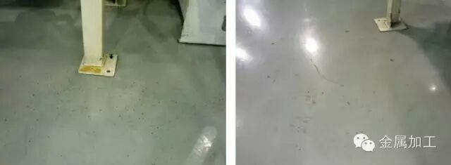
In order to avoid this phenomenon, a well-known auto parts manufacturer used the cutting fluid in his crankshaft production line to avoid oil leakage. In order to avoid this phenomenon, Quaker recommended that they try QUAKERCOOL® 3502 and To replace the original cutting fluid products. After a period of trial use, Quaker's QUAKERCOOL® 3502 is more effective in controlling oil mist than other comparable products.
The QUAKERCOOL® 3502 offers excellent product performance and productivity, saving 38% in annual product cost compared to customers' original products and saving 45% in annual product cost compared to other trial products.
5) Crankshaft flange hole machining
For the machining of crankshaft flange holes. In the drilling process, a solid carbide step drill is often used, which is suitable for high-precision drilling. Tapping is often done with new solid carbide cutting taps and extrusion taps. Taps specially designed for the processing characteristics of different materials are generally used.
In the tapping process, the stalk problem of the tap is often encountered, and OSG provides a corresponding solution.
Case recommendation 4: tap
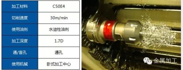
The original processing material was QT700-2, and the customer used the M12X1 recommended castings with straight groove taps, which is ideal for processing. However, due to process changes, the customer changed the material to steel No. 50 steel, because steel parts are not suitable for processing with straight groove taps, spiral groove taps and edge angle taps are more suitable. Sure enough, stalking problems occurred at the beginning of processing. Considering the new processing environment and processing materials, the OSG removes the coating at the front corner of the tap without changing the tap, leaving the coating on the rest. The chip removal method of straight groove taps is generally based on breaking chips. Although the coating can increase the rigidity of the tool itself, it also reduces the friction coefficient between the tool and the workpiece, resulting in chip winding. Therefore, the removal of the coating at the front corner can effectively improve the chip breaking ability of the straight groove tap. The test result is 100 pieces higher than the customer's required life and is recognized by the customer.
We have many models clamp Led Plant Light, 1/2/3/4 head, circle model, bar model, and another model clamp Full Spectrum Led Lights. Easy installed, you can clip on everythere, works well for home depot, vegetables, hydroponic growth.
LED Grow Light Benefits:
More efficient: 100% of the power input for our LED grow lights is used for your plant chlorophyll production.
Better for environment: It saves 50% to 90% in energy consumption compared to incandescent bulbs or fluorescent tubes.
Less Heat: Low heated LED bulbs will protect your plants well.
Less trouble: No ballast to burn out likes other plant lights
No maintenance costs and 50,000 hours lifetime
Easy to install and use, plugging into the electric outlet directly


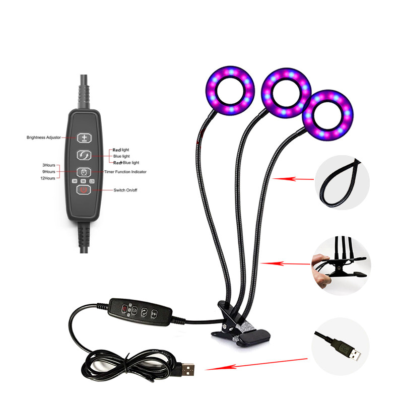
Led Grow Lights Commercial,Indoor Clamp Grow Light,Outdoor Plants Clamp Grow Light,Led Greenhouse Grow Light
Shenzhen Wenyi Lighting Technology Co., Ltd , https://www.wygrows.com