Foreword
This standard is based on the “Notice of the Second Batch of Industry Standards (Repair) Planning in the Energy Sector issued in 2011 by the National Energy Administration†(National Energy Technology (2011) No. 252).
This standard is drafted in accordance with the rules given in GB/T 1.1-2009 "Standardization Guidelines - Part 1: Standard Structure and Compilation".
This standard is proposed and managed by the China Electricity Council.
This standard was drafted by: China Electric Power Research Institute, State Grid Electric Power Research Institute, Beijing Qunling Energy Technology Co., Ltd.
The main drafters of this standard: Huang Jingsheng, Zhang Junjun, Qin Yudi, Niu Chenhui, Li Yu, Chen Zhilei, Wang Jianqiu, Liu Meiyin, Wu Hao, Li Hongtao, and Zhang Jinbin.
The opinions and suggestions in the implementation process of this standard are fed back to the Standardization Management Center of the China Electric Power Enterprise Federation (No. 1 Article II, Baiguang Road, Beijing, 100761).
1 Scope
This standard specifies the detection conditions, detection equipment, and detection methods for anti-islanding effect of photovoltaic power generation systems.
This standard applies to access to the power grid through the 380V voltage level, and access to the user-side new, expansion and reconstruction of the photovoltaic power generation system through the 10 (6) kV voltage level.
2 normative references
The following documents are indispensable for the application of this document. For dated references, only dated versions apply to this document. For undated references, the latest version (including all amendments) applies to this document.
GB 1207 electromagnetic voltage transformer (GB 1207-2006, IEC 60044-2: 2003, MOD)
GB 1208 Current Transformer (GB 1208-2006, IEC 60044-1: 2003, MOD)
GB/T 29319 photovoltaic power generation system access distribution network technical regulations
3 Terms and Definitions
The following terms and definitions apply to this standard.
3.1
Photovoltaic system
Utilizing the photovoltaic effect of photovoltaic cells, a solar power system that converts solar radiation directly into electrical energy.
3.2
Islanding
Part of the power grid, which includes the load and power supply, continues to operate in isolation after being detached from the main network. Isolated islands can be divided into unplanned islands and planned islands.
Note: Unplanned islands are unplanned and uncontrolled islands. Planned islands are islands that are planned to produce islands based on preconfigured control strategies.
3.3
Quality factor
Qf
A representation of the degree of resonance of the island test load.
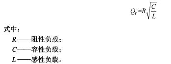
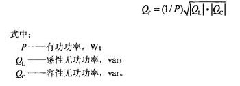
When C and L are tuned to the grid fundamental frequency, Qf can be obtained from the active power P, inductive reactive power QL, and capacitive reactive power QC of the resonant circuit:
3.4
On-line point of the internet
For a photovoltaic power generation system with a step-up transformer, it refers to a bus or a node on the high-voltage side of a step-up transformer; for a photovoltaic power generation system without a step-up transformer, it refers to the output summary point of a photovoltaic power generation system.
4 detection conditions
The test shall be carried out under the following conditions. Before the start of the test work, the relevant data shall be measured according to the following requirements and filled in the test report. The non-conformances in the test conditions shall also be recorded while recording the data.
a) Photovoltaic power generation system should be tested within half a year after the completion of the overall acceptance;
b) The photovoltaic generation system equipment is in normal operation;
c) Testing should be carried out under sunny conditions with few clouds.
5 testing equipment
5.1 AC load
The AC load should consist of adjustable resistors, inductors, and capacitors in parallel. The load should meet the test requirements. If using a core inductor, the total harmonic distortion of the inductor current (THD) should not exceed 2% when operating under nominal voltage conditions.
5.2 Measuring device
The specifications of voltage and current measuring devices involved in this standard shall at least meet the requirements of Table 1. Voltage transformers shall meet the requirements of GB 1207, current transformers shall meet the requirements of GB 1208, and the sampling frequency of data acquisition systems shall not be less than 10 kHz.

6 detection methods
6.1 Sampling principle
a) For photovoltaic systems that only have a single inverter and the inverter has passed the anti-islanding test may not be tested.
b) For PV systems with multiple grid points, the inverters shall be classified according to the model of the inverter they are equipped with. Each subsystem shall randomly select one grid point for testing.
6.2 Detection Circuit
Anti-islanding effect detection circuit diagram shown in Figure 1, the AC load should be connected to the photovoltaic power generation system and the network point.
6.3 Detection Procedure
Anti-islanding detection should be performed at the grid connection point of the photovoltaic power generation system as follows:
a) Close the switches Si and S3 and turn off the switch S2 so that the photovoltaic power generation system can maintain stable operation.
b) Measure the active and reactive power of the PV system under test by means of a power measuring device.
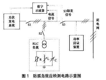
c) Close the switch S2 and in turn load the AC load inductance L, capacitor C and resistance R so that:
1) The reactive power consumed by the LC is equal to the reactive power emitted by the PV system under test;
2) The active power consumed by the RLC is equal to the active power emitted by the measured photovoltaic power generation system;
3) The quality factor of the RLC resonant circuit is 1±0.2;
4) The fundamental current flowing through S3 is less than 5% of the measured output current of the PV system.
d) Switch S3 is turned off, and the time from stopping switch S3 to stopping the power supply to the AC load from the photovoltaic power generation system is recorded by a digital oscilloscope.
If the measured photovoltaic power generation system stops supplying power to the AC load within 2 seconds, it will no longer continue to detect; otherwise, the next step should be performed.
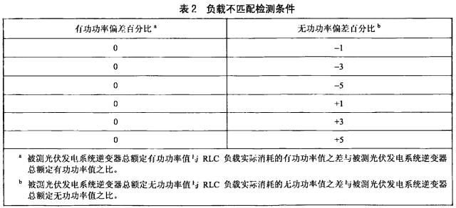
e) Adjust the inductance L and capacitance C so that the reactive power of L and C changes by ±2% each time as specified in Table 2. The parameters in Table 2 indicate the direction of the reactive power flow through the switch S3 in FIG. 1 , and the positive sign indicates the power flow from the measured photovoltaic power generation system to the power grid.
f) After each adjustment, disconnect S3 and record the running status of the tested photovoltaic power generation system through a digital oscilloscope. If the recorded time shows a continuous upward trend, the adjustment range should be expanded by 2% increments until the recording time is presented. Downward trend.
Note: The purpose of this test is to test the anti-islanding effect of photovoltaic power generation systems. The test should be such that the RLC load resonates at the rated operating frequency of the PV system. The impedance, inductive reactance, and capacitive reactance of the photovoltaic system itself should be part of the RLC load.
7 detection files
7.1 Checking the Content of the Document
7.1.1 Test results should be recorded and include the following:
a) Basic information of the measured photovoltaic power generation system;
b) test equipment specifications;
c) site detection of environmental parameters;
d) Test results of the tested photovoltaic power generation system under test conditions;
e) Other related content.
7.1.2 Test results should be able to repeat the verification. The test results shall be recorded in the original record form at the scene and the original record form shall be signed by the inspection personnel, the verification personnel and the technical responsible personnel.
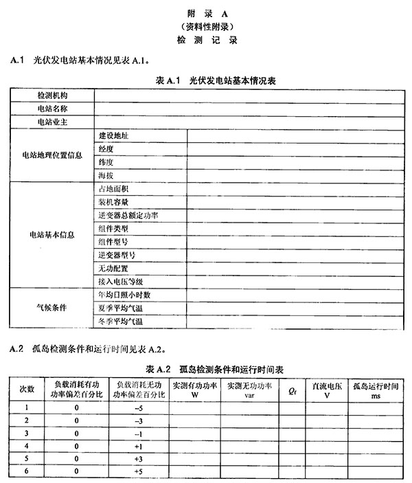
7.2 Inspection Record
Test record format See Appendix A.
Rustic emitation aluminum coil
Aluminuim is the most abundant metallic element in Earth's crust and the most widely used nonferrous metal. Aluminum is a silver-colored, low density metal. It is used in a huge variety of commercial applications. Rustic emitation aluminum coil is also called corten prepainted aluminum coil, it's an imitation of aged metal, like rustic on the sheet surface. It offers more choices to the designers and give a different stunning looks of the building. The substrate could be aluminum alloy 1100 1060 3003 3004 3105 3005 5052 5005, etc. the paint is PVDF coating, coating thickness is 35 microns, we offer 20 years warranty on the PVDF coating
Color Aluminum Coil,Colored Aluminum Coil,Corten Prefinished Aluminum Coil,Prefinished Aluminum Coil
Shandong Wofeng New Material Co., Ltd. , https://www.wofengcoil.com