1. Set the "roughing parameters". Click [Apply] - [Track Generation] - [Contour Rough Machining], set "Roughing Parameters" in the pop-up "Roughing Parameters Table", and set the roughing "milling parameters", as shown in Figure 6. .
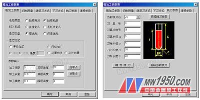
Figure 6 roughing parameter settings
2. Set the roughing "cutting amount" parameter.
3. Confirm the default values ​​of the "reverse and retract mode", "below knife mode", and "clear root mode" system. Press "OK" to exit the parameter settings.
4. Pick up the machining contour as prompted. After picking the rectangle that sets the machining range, click the chain search arrow; press the system prompt “Pick the machining surfaceâ€, select the entire solid surface, the system will turn all the picked surfaces to red, and then press the right mouse button to end.
5. Generate a roughing tool path. The system prompts: "When preparing the surface, please wait", "Processing the surface", etc., and the system will automatically generate the roughing track. The result is shown as 7.
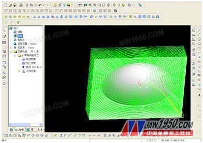
Figure 7 generates the roughing tool path
6. Hide the resulting roughing track. Pick the track, click the right mouse button and select the [Hide] command in the pop-up menu to hide the generated roughing track for the next step.
3.2 Parameter line finishing tool path
1. Set the surface area processing parameters. Click [Application] - [Track Generation] - [Parameter Line Processing], and set the finishing parameters in the pop-up "Parameter Line Finishing Parameter Table", as shown in Figure 8.
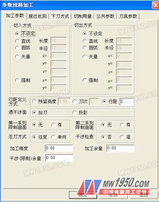
Figure 8 finishing parameter settings
2. Select the machining surface. According to the prompt, select the complete surface of the machining and generate the trajectory as shown in Figure 9.
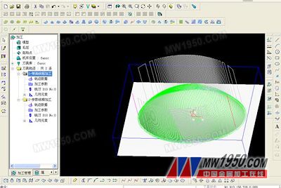
Figure 9 finishing tool path
3.3 Processing simulation, tool path inspection and modification
1. Press "Visible" ammonium twist to display all generated coarse/finish traces.
2. Click [Application] - [Track Simulation], select the option in the immediate menu, as shown in Figure 10; press the system prompt to pick up the roughing tool path and finishing track at the same time, press the right button; the system will perform simulation processing. During the simulation, the system displays the way of walking. After the simulation is finished, pick the point to observe the section as shown. Press the right button to store the simulation results.
2 Observe the simulated machining path and check whether the cutting path is correct and reasonable (with or without overcutting).
3 Click [Apply] - [Track Edit], pop up the "Track Editing" table, pick up the corresponding machining track or corresponding track point according to the prompt, modify the corresponding parameters, and modify the local track. If the modification is too large, the machining path should be regenerated.
4 After the simulation test is correct, the rough/finishing track can be saved.
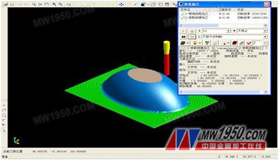
Figure 10 machining trajectory simulation
3.4 Generating G code
1. Click [Apply] - [Post Processing] - [Generate G Code], and give the NC code file name (semi-ellipsoid.cut) to be generated and its storage in the pop-up "Select Post File" dialog box. Path, press "OK" to exit.
2. Pick the roughing path and the finishing path separately, and press the right button to determine the machining G code.
3.5 Generate processing order
There are three purposes for generating a processing order: First, the need for processing in the workshop. When there are many processing procedures, the processing can be organized and there is no confusion. The second is to facilitate the communication between the programmer and the machine operator. The things spoken by the mouth are not as clear as the words on the paper. The third is the need for workshop production and technical management. The graphic file and G code program of the finished workpiece can be saved together with the processing technology. If the workpiece needs to be processed again after one year, it can be taken out and processed immediately. It is very clear that there is no need to do repeated work.
Select [Application] → [Post Processing] → [Generate Process Order] command, pop up the Select HTML File Name dialog box, enter the file name and press OK. At the bottom left of the screen, you will be prompted to pick up the machining path. Use the mouse to select or use the window to select or press the “W†key to select all the tool tracks. Right click to confirm and immediately generate the machining process sheet. The processing technology list can be viewed with IE browser, and can also be viewed with WORD and can be modified and added with WORD.
At this point, the modeling of the semi-ellipsoid diagram, the generation of the machining trajectory, the simulation of the machining trajectory, the generation of the G code program, and the production of the machining process sheet have all been completed, and the machining process sheet and the G code program can be sent to the workshop through the factory LAN. It is. Before the processing, the workshop can also pass the check G code function in CAXA Manufacturing Engineer, and then look at the shape of the processing code, so that there are several chests before processing. Find the workpiece zero according to the requirements of the processing list, and then install the tool according to the requirements in the process sheet to find the Z-axis zero point of the tool, and you can start machining.
Previous page
Kitchen Sink Faucets,Touch Kitchen Faucet,Retractable Kitchen Faucet,Black Steel Hose Faucet
Yuyao Zelin Sanitary Ware Co., Ltd , https://www.kitchen-sinkfaucets.com