 |
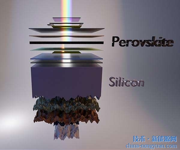
The perovskite layer does not need to cover the entire surface but reveals holes. Scientists can already prove that it has established a protective layer against short circuits.
Metal-organic perovskite layers for solar cells are generally manufactured using a spin coating technique on a compact substrate. These perovskite layers usually have many holes, but they can achieve amazing levels of efficiency. These holes do not cause a significant short circuit between the front and back contacts, and the HZB team led by Dr. Marcus Baer has now discovered the cause. Marcus Baer collaborates with the team led by Professor Henry Snaith (Oxford University) of BESSY II.
The conversion efficiency of early metal organic perovskites was only a few percent (2.2% in 2006). However, progress has been rapid, and the current record level has been much higher than 22%.
The efficiency of commercial silicon solar cell technology has been continuously improved for more than 50 years. Films made from low cost metal-organic perovskites can be produced on a large scale by spin coating and subsequent baking (thus solvent evaporation and material crystallization), which will make the technology more attractive.
Perforated hole in perovskite film
Despite this, the thin perovskite films produced on spin-on compact substrates are generally not perfect, but rather exhibit many pores. These loopholes were also found in samples of the pioneering perovskite group led by Prof. Henry Snythes. The problem is that these holes can cause adjacent layers of solar cells to come in contact with each other and cause short-circuiting of the solar cells. This will greatly reduce the level of efficiency that was not previously observed.
Build a thin layer
Now, Marcus Bar and his team and the Spectro-Microscopy team at the Fritz Haber Institute carefully examined Henry Snaith's samples. Through electron microscopy, they mapped the surface morphology. The chemical composition of the pore area was then analyzed using the BESSY II spectroscopic method. We can prove that the substrate is not actually exposed even in the hole. And obviously, the deposition and crystallization process there prevents short circuits, explains Dr. Claudia Hartman.
Prevent short circuit
At the same time, the scientists were able to determine that the energy barriers that the charge carriers had to overcome could only recombine with each other when the contact layer was directly encountered. The transport material of the electron transport layer (TiO2) and the positive charge carrier (Spiro MeOTAD) are not actually in direct contact. In addition, the composite barrier between the contact layers is sufficiently high that, despite the presence of many holes in the perovskite film, these cause the internal loss of the solar cell to be extremely small.
(Original from: Daily Solar)
Features
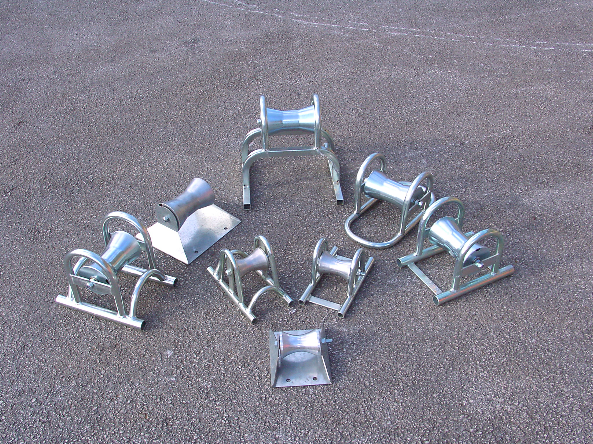
1. In the cable laying process, it can support the cable and change the sliding friction into rolling friction between cable and support, which means it can reduce pulling force.
2. Straight pulling roller is used in the straight line segment of cable laying. Generally put one roller every 2-3 meter.
3, Corner pulling roller is used in the turning point of cable laying. The amount of corner pulling roller in the turning point is determined by the side pressure and cable bending radius.
Usually used in laying path of cable tray, well head, upper and down slope and control cable.
Notes: When operating, the roller should be fixed in ground or other supports.

Cable Roller,Corner Roller,Hoop Roller,Cable Guide Roller
NINGBO MARSHINE POWER TECHNOLOGY CO., LTD. , https://www.marshine-power.com