Do not be greedy and cheap to strengthen the wooden floor to buy "Nine Aspects"
The material stress-strain relationship is to reduce the amount of program calculation. The simplification of the finite element model is as follows: (1) This section mainly studies the force performance in the plane of the joint interface of the extended end plate, regardless of the out-of-plane buckling of the beam-column member. The structure is symmetric about the centerline of the web of the beam and column, and only half of the model is established.
(2) Considering the bolt as a whole, and because the bolt head and the nut are always in close contact with the end plate during the whole loading process, the bolt head and the nut are not considered for contact analysis with the end plate and the column flange, and the It is tightly bonded to the end plate and the column flange. Considering the contact between the column flange and the end plate, the contact surface is connected by a 3D contact unit.
(3) The welding of the end plate and the flange flange and the web of the extension end plate is considered to be bonded together in the calculation. The effects of joint welds, high-strength bolts and welding residual stresses were neglected, and welds and weld vents were not simulated.
The extended end plate is connected to the node for meshing the graphics. The X and Z direction constraints are applied to the top of the column, and the X, Y, and Z directions (coordinates) are applied to the bottom end, and symmetric constraints are applied to the center plane of the beam and column web. The analysis of the node is divided into two stages: the first stage is the bolt preloading stage, the pretension of the bolt is taken to the standard value, the pretension of the bolt is realized by the pretensioning unit (Prets179); the second stage is the axis applied at the end of the column. Pressure; the third stage applies a concentrated load at the beam end. The Von2Mises yield criterion is adopted, and the multi-linear follow-up strengthening criterion is adopted in the strengthening stage. The geometric nonlinearity is considered in the elastic and plastic loading stages. To obtain the stress distribution, the Newton2Raph2son method is adopted.
The definition of the relevant parameters The joint surface angle (relative rotation angle of the beam and column) φ is composed of the column flange deformation, the model end plate deformation and the bolt deformation, and the joint surface rotation angle is calculated by the formula (1): φ=/(hb-tbf)(1 Where: Xc1, Xc2D beam lateral height at the center height of the column web and wing edge line (middle X-direction displacement); Xb1, Xb2D beam tension flange and pressure flange center end plate Side shift; hbD beam height; tbfD beam flange thickness.
R'in is the origin rotational stiffness of the joint surface (the origin tangent modulus of the M2φ curve); Rin is the initial rotational stiffness of the joint joint surface (the joint bending moment of the M2φ curve according to EC3 is the full plastic bending moment of the beam section 2/3 The secant stiffness corresponding to the time).
Rin and R'in are calculated by the formula (2)(3)(4): Rin=Mb/φb(2)Mb=2Mpb/3(3)R'in=M0/φ0(4) where: φbDM2φ curve The joint faces are subjected to the bending angle of the joint surface when the bending moment is Mb; the initial rotational stiffness of the SjD node; the θD node rotation angle is composed of the deformation of the node domain, the deformation of the column flange, the deformation of the end plate and the deformation of the bolt. θ, Sj are calculated by equations (5) and (6): θ = (Xb1 - Xb2) / (hb - tbf) (5) Sj = Mb / θb (6) where: when the node is subjected to a bending moment of Mb in the θbDM2θ curve The corresponding node corner.
The finite element calculation results are compared and analyzed (1) the joint rotational stiffness and ultimate bearing capacity. Comparing nodes TB3, NB1, NB2 and NB3 can be obtained: as the column axial pressure ratio increases, the P2△ effect increases, and the column deformation increases; the initial rotational stiffness of the node decreases (eg, for Sj, NB1 versus TB3) Reduced by 1.8%, NB2 decreased by 2.5% relative to NB1, NB3 decreased by 15.5% relative to NB2), and the ultimate bearing capacity decreased (NB1 decreased by 4.7% relative to TB3, NB2 decreased by 8.6% with respect to NB1, and NB3 decreased by 12.7% with respect to NB2); The vertical displacement of the loading point is increased, and the relative limit rotation angle of the beam and column is reduced. This is because the deformation of the column is also large. From φ=φb-φc, the relative rotation angle φ of the beam and column is small. The greater the column axial compression ratio, the faster the initial rotational stiffness of the joint decreases, and the greater the reduction of the unidirectional loading capacity of the joint.
It can be seen that when the axial pressure is relatively small (Nc/Ncy ≤ 0.4, where Nc and Ncy are the axial pressure and axial yield bearing force of the column, respectively), the column axial pressure ratio has little effect on the bearing capacity of the joint. When the column axial pressure ratio reaches 0.6, the bearing capacity of the joint drops more, and attention must be paid to the design. According to the results calculated from the four test pieces, the relationship between the axial compression ratio of the beam-column end plate connection column and the bearing capacity of the joint is the first phase of Liu Yingyun et al.: The column axial pressure ratio is high-strength bolt line for the beam and column, and the formula is obtained by linear regression. ): Mp = 0. 9581-1. 1666Nc / Ncy2 (0 ≤ N / Ncy ≤ 0. 6) (7) where: MpD node TB3 limit bending moment under monotonic load. (2) The failure mode of the node. The destruction mode of the node.
Node failure mode specimen number failure mode <1> TB3 first and second row bolts are yielded, the column area of ​​the node section yields, the end plate yields semi-ductile failure, the NB1 node area column yields, the end plate pulls off the column flange And the buckling at the joint of the beam flange, the first and second rows of bolts are stretched and yielded to the semi-ductile failure NB2, NB3 column flange yielding, the end plate and the beam flange joint yield, the compression zone screw and nut joint yield semi-ductile failure 3 Conclusions By analyzing the performances of the unidirectional loading of the joints of the high-strength bolts of the beam-column high-strength bolts under the four column axial compression ratios, the following conclusions are drawn: (1) The axial compression ratio of the column increases, and the initial rotation of the nodes The stiffness is reduced; the larger the column axial pressure ratio, the faster it is lowered. (2) The axial compression ratio of the column increases, and the unidirectional ultimate load carrying capacity of the joint decreases; the larger the axial compression ratio of the column, the larger the reduction. It must be noted that the column shaft pressure ratio should not be too large. (3) The relationship between the axial pressure of the beam-column end plate connecting column and the bearing capacity of the joint: Mp=0.
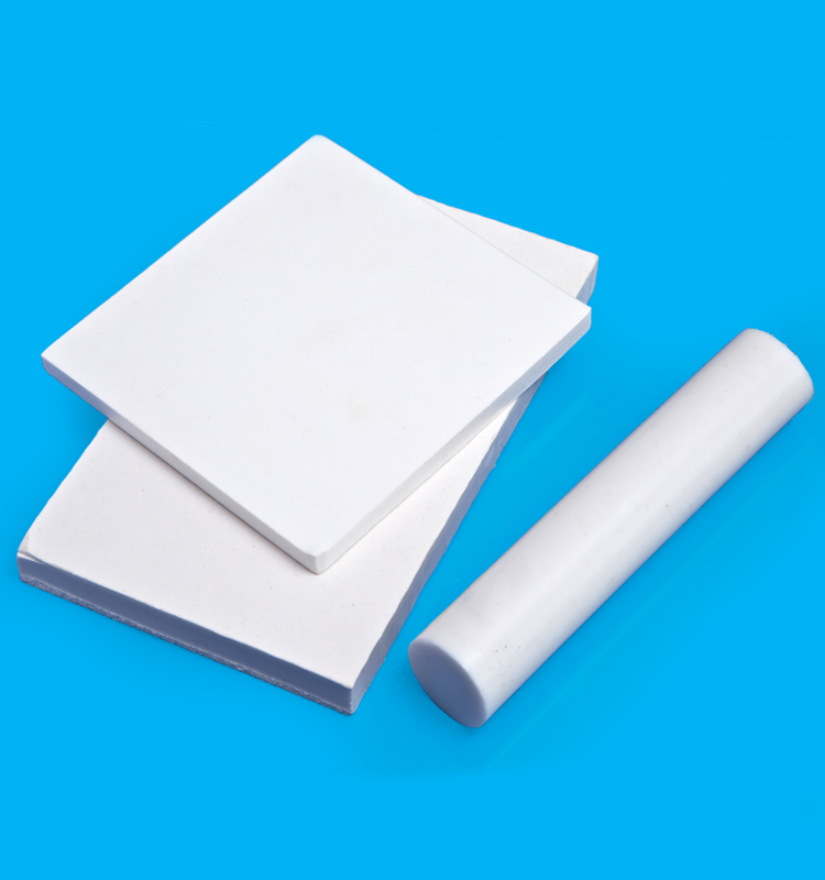
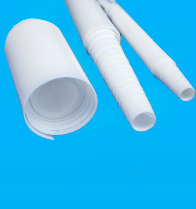
PTFE molded sheet is manufactured by molding method with PTFE granular resin. In fluoroplastics, PTFE got the most consumption and was used widely. It`s an important material in variety of fluoroplastics,like teflon ptfe tape,ptfe teflon tape. PTFE exhibits astonishing chemical resistance. This self-lubricating material provides a low friction coefficient, and is ideally suited for the manufacture of corrosion-resistant gaskets & seals.
Applications :
• Seal, seats, packing, chevrons
• Piston rings, glide rings, lantern rings, back up rings, Slide bearings
• Electrical and thermal insulators
• Wear plates
• Bushes, bearings in chemical pumps
• O-rings, envelope gaskets
• Bellows, lings(chemical), valve seats
Key Features :
• Excellent chemical and heat resistance
• Lowest co-efficient of friction
• Highest operating temperature and stability
• Physiologically inert
• Excellent electrical properties
• Can have glass or bronze fillers for wear resistance


Ptfe Sheet,Ptfe Rod,Teflon Rod,Teflon Sheet
SHENZHEN XIONGYIHUA PLASTIC INSULATION LTD , http://www.xyhplastic.com